Are there a couple is misprints in the low pass MFB filter?
I see two capacitors marked in mF, whereas all the others are in nF.
The lower supply rail electrolytic is shown with +side attached to the -30Vdc !
The high pass is operating on +-30Vdc supply rails. There is adequate headroom for high level transients.
The low pass is operating on +-15Vdc supply rails, that reduces the headroom significantly, maybe -6dB.
There is a summing stage at the input and this stage is set to a gain of +6dB. That gives a gain of +12dB which when combined with the lower supplies effectively means the low pass stage will overload with signals ~18dB lower than the high pass.
Is this the right way to do it?
Last edited:
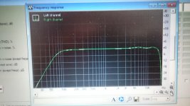
I had limited time to do any measurements...I still need to order some capacitors to fine tune the high pass crossover frequency. I am looking for 150Hz.
I am not building the low pass, I have few boards from ebay with variable crossover frequency just for sub.
Well, the critical is Re or that 100 ohm resistor in first buffer. That affects the distortion spectrum. My external sound card is not recognized by my old laptop anymore, where I have measuring software, like holm, rew or right mark...so I am using just the headphone output and line in/mic input on crappy laptop. Just a loop out/back in is showing distortion, crappy convertors.
Anyway, I can definitely see the second harmonic missing. With Re being high, like 1-2k ohm, distortion is about 0.8%, which is too high. Going down with value to few hundred ohms distortion drops to 0.1%, with just 120 ohm distortion is about 0.07%, but this in reality is lower, since my laptop is adding its own. I did not continue lower...first I need to get better laptop with external sound card.
Ada,
the two 100nF on the output are almost operating as filters of the audio band.
F-3dB ~80Hz when feeding into 100k.
If you feed into 10k, then you should be using ~1000nF to get the filtering effect far enough below the 100Hz audio band and thus avoid audio band distortion.
the two 100nF on the output are almost operating as filters of the audio band.
F-3dB ~80Hz when feeding into 100k.
If you feed into 10k, then you should be using ~1000nF to get the filtering effect far enough below the 100Hz audio band and thus avoid audio band distortion.
I guess there should be one more buffer on the output, since it uses one more high pass, to decouple it from next stage...
Exactly what I said.
")
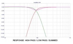
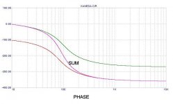
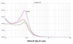
As promised, here are the plots for the response of that (corrected) circuit,
showing the high pass, low pass and summed for the parameters of
frequency response, phase response, and group delay.
I don't think I made any errors, but feel free to point them out.....
showing the high pass, low pass and summed for the parameters of
frequency response, phase response, and group delay.
I don't think I made any errors, but feel free to point them out.....
Attachments
Original Kaneda 4 way active filter DIY publication
Amusing vintage solid state active filter.

Thanks Soundhappy for all the beautiful pictures, glad to see you back!
Thank you guys....here is the link
Filtre électronique triphonique de type Kanéda (JC.Gaertner)
Filtre électronique triphonique de type Kanéda (JC.Gaertner)
- Status
- This old topic is closed. If you want to reopen this topic, contact a moderator using the "Report Post" button.
- Home
- Source & Line
- Analog Line Level
- active crossover Kaneda