Any reason why you are missing out Q3 and Q4... although I think I can see what you have done ")
On the 4017 you use the outputs in sequence, otherwise you will have a 'dead' button push as a non used output becomes active.
So you use Q0 to Q4 to drive the ULN2003. Use Q5 to provide the reset.
On the 2003, it doesn't matter which sections you use as they are all independent. Normally you would use whatever makes the board layout easiest.
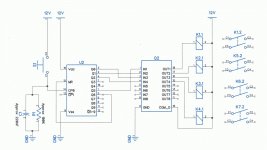
Oops, I went with the pin numbers instead of the Q#s, does this look better
Is there a way to set this up with 2 coil latching relays? E.g. connecting a single 4017 output to two 2803 inputs (accounting for mA limits) so as one relay sets the previous one resets?
Is there a way to set this up with 2 coil latching relays? E.g. connecting a single 4017 output to two 2803 inputs (accounting for mA limits) so as one relay sets the previous one resets?
Attachments
Old fashioned telephone exchange uniselector....
Yes; but awful hard to find now. Also typically much more than 3 throws. You could strap the contacts 123123123... but if it is not a multiple of 3 you get "dead" or "skip" at non-obvious intervals. You can wire excess contacts to pulse-pulse to quick-skip those points; may be an unnerving racket at odd times. Otherwise the PERFECT solution.
Modifying a 4/8 position ratchet with 3-lump cams may be as easy.
https://archive.org/details/TheDesignOfSwitchingCircuits is dense with relay logic but does not address a simple counter. It has several flip-flops and two of these could be decoded to 4 positions easy, 3 with a little thought.
Just for fun: with just 4 transistors (and lots of passives), you can build a ring counter.
Here is a seven-output example:
Good idea.
That looks better.
You could add an invertor stage between a 4017 output and an 2003 input. That would allow two relays to be driven, so that whatever one is doing, the other isn't
I thought afterwards (and forgot to update the thread) that you don't need an invertor, just daisy chain the 2003 stages feeding the second from the output of the first. No extra parts required.
Oops, I went with the pin numbers instead of the Q#s, does this look better
Is there a way to set this up with 2 coil latching relays? E.g. connecting a single 4017 output to two 2803 inputs (accounting for mA limits) so as one relay sets the previous one resets?
Thanks for this! One question: What are Kx.1's? Diodes? And S1 is the button correct?
BTW, sorry for my absence. I didn't see all of these replies come into my email, but I appreciate all the help. I'm going to go ahead and order these as I think I will have time to build this preamp as my work has slowed down for a little bit.
Any cooking grade 4017 should be fine. Just check the details as often different letters can mean different package outlines. Same for the 2003. Just check the data sheets and be sure.
Ok thanks
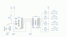
Ok, I've tried for a while to get this working, but I'm not having any luck. The 4017 is not counting, but Q0 has a constant 12V on it regardless of button push. Even with that pin high though, there is no voltage on pin 16 of the 2003.
I'm guessing I did something wrong (see circuit)
Help would be much appreciated! Thanks!
I'm guessing I did something wrong (see circuit)
Help would be much appreciated! Thanks!
Attachments
Ok, I've tried for a while to get this working, but I'm not having any luck. The 4017 is not counting, but Q0 has a constant 12V on it regardless of button push. Even with that pin high though, there is no voltage on pin 16 of the 2003.
I'm guessing I did something wrong (see circuit)
Help would be much appreciated! Thanks!
There is no pull down resistor on 4017 switch input.
There is no pull down resistor on 4017 switch input.
Ok, about 1K? In series with the switch before it connects to CLK? What does this resistor do?
I also tried it with // 220uf/100K from switch/clk to ground. Forgot to include in the circuit
THanks
Ok, about 1K? In series with the switch before it connects to CLK? What does this resistor do?
I also tried it with // 220uf/100K from switch/clk to ground. Forgot to include in the circuit
THanks
The switch pulls the signal up to 12 volts.
The 4k7 resistor pulls it down to ground.
Without a resistor the input floats when switch not pressed.
You will need a small capacitor across the pull down resistor to stop switch bounce causing multiple clock pulses.
The switch pulls the signal up to 12 volts.
The 4k7 resistor pulls it down to ground.
Without a resistor the input floats when switch not pressed.
You will need a small capacitor across the pull down resistor to stop switch bounce causing multiple clock pulses.
Ok, so the the resistor connects from CLK to GND?
Like I said, I did try it with 100k clk/switch to ground with 220uf across it. No luck. Are the values just wrong or should that have worked?
Ok, so the the resistor connects from CLK to GND?
Like I said, I did try it with 100k clk/switch to ground with 220uf across it. No luck. Are the values just wrong or should that have worked?
Yes 4k7 resistor to ground with 10uf in parallel with resistor.
- Status
- This old topic is closed. If you want to reopen this topic, contact a moderator using the "Report Post" button.
- Home
- Source & Line
- Analog Line Level
- Help with one button relay input switching