As currently laid out your input static protection will be compromised by the inductance of the long thin tracks back to the power rails. As you want the ESD to return to is source via the ground plane on a two layer PCB the best way to achieve this would be to combine the diode with capacitors on the +/- rails by each one of the diodes that way there is a low impedance return path for the static event.
Depending on the level of protection you require you could simply eliminate them. The imput impedance offers quite high Static protection and the diodes were put in as comercial designs require a very high level of esd protection to avoid customer returns from dry environments.
Depending on the level of protection you require you could simply eliminate them. The imput impedance offers quite high Static protection and the diodes were put in as comercial designs require a very high level of esd protection to avoid customer returns from dry environments.
Last edited:
I think this is the input stage from an ARCAM A85 amplifier. I used to be the design manager there and think I recognise it.
You're absolutely right. I took it from A32 service manual but I've checked and A85 has exactly the same input stage. Thank you very much for your input. It's very interesting to know how and why decisions were made.
As currently laid out your input static protection will be compromised by the inductance of the long thin tracks back to the power rails. As you want the ESD to return to is source via the ground plane on a two layer PCB the best way to achieve this would be to combine the diode with capacitors on the +/- rails by each one of the diodes that way there is a low impedance return path for the static event.
Depending on the level of protection you require you could simply eliminate them. The imput impedance offers quite high Static protection and the diodes were put in as comercial designs require a very high level of esd protection to avoid customer returns from dry environments.
I've looked at the Arcam's preamp board layout in service manual (it doesn't show traces unfortunately, only the layout of components) and it seemed to me that esd protection diodes are located quite far from one another and that they are also quite long there.
Unfortunately I don't quite get the idea with the capacitors in combination with diodes. Do you mean to put them between power supply rail and the ground next to each diode?
Yeah, large C0G caps cost a fortune and are huge, but they're still tiny compared to a film and a lot cleaner, unless you spend a lot of money. Still, you do not need anything above 0.1µF for a servo - using an output attenuator to reduce the servo loop gain will lower the effective highpass frequency. In a servo I'm working on now, I'm using around 60K and 0.1µF, and I get an overall high pass corner of 1Hz because the servo output is attenuated back into the amplifier it's correcting. That also solves a lot of other problems, such as minimizing the servo amp's LF noise, which is injected back into the controlled op amp.
It's best to use a simulator like LTspice to verify the response of these circuits, since the calculations can get complicated, and at the very least, it's nice to have confirmation that what you think is happening is actually happening.
Surprisingly I can understand almost everything that you've wrote.
") You're explaining it very good. Thank you!
You're explaining it very good. Thank you!Unfortunately I don't know the theory behind the dc servo circuit so I don't quite get how to make the attenuator and how it can affect circuit. I understand the basic principle of dc servo, that an integrator would make an average of the signal which will be the dc offset and will supply it back to the op amp and shifting the output to stay at 0 offset. But I don't know why the values of feedback capacitor and input and output resistors are chosen this way and how it is calculated.
A bit of off topic but related to dc servo circuits. My power amp that I'm going to use is also using dc servo circuit. It is basically LM3886 bridged-parallel amplifier so it uses dc servos at each chip to prevent amplifier chips from fighting each other. I've bought ready made PCBs for that and they also use 0.47uF capacitors in the feedback of the servo op amp but the component that should used to be there is 0805. So the only capacitor with that value and package size appeared to be X7R ceramic. Is it ok to use X7R there. How can it affect the circuit in this application compared to C0G? I don't know if it matters but amplifier chips and dc servos are in non-inverting configuration there.
The A32 is a 4 layer PCB and the return path for the ESD diodes is enhanced by that. In a two layer design you need a way to ensure that the ESD strike becomes common mode as fast as possible. To do this you couple the power lines to the ground plane at high frequency with capacitors.
This way if you get an ESD strike the energy ends up on all the parts of the circuit together causing a short common mode lift in voltage. Rather than rushing through the electronics to get to the lower potential points causing damage.
As I said earlier if you are relatively careful about static you can get away without these parts. But for your interest I have shown a possiblle placement sharing caps beween diodes to reduce the number required.
Attachments
The A32 is a 4 layer PCB and the return path for the ESD diodes is enhanced by that. In a two layer design you need a way to ensure that the ESD strike becomes common mode as fast as possible. To do this you couple the power lines to the ground plane at high frequency with capacitors.
This way if you get an ESD strike the energy ends up on all the parts of the circuit together causing a short common mode lift in voltage. Rather than rushing through the electronics to get to the lower potential points causing damage.
As I said earlier if you are relatively careful about static you can get away without these parts. But for your interest I have shown a possiblle placement sharing caps beween diodes to reduce the number required.
Thank you. Now I'm starting to understand how ESD protection works. Probably I'll remove this protection because as you said it was done primarily for dry countries and I live probably in one of the most wet places in the world
But I'm interested in how to choose values for these capacitors.
Typically the performance of capacitors in this application is limited by the inductance of the capacitor and its pad and PCB layout. The situation is complicated by the conflicting requirements of the component. To withstand the inital strike voltage you want a very high breakdown voltage, however to have low inductance you want as small a part as possible and to have the minimum reduction in capacitance due to the voltage you want a stable dielectric like cog. In a situation like this I would guess 470pF in 0603 at as high a voltage as was reasonable in price would be a reasonable compromise. However to be sure I now simulate an ESD strike using LTSpice and optimise the protection that way, it can be quite counter intuative how the circuit will behave.
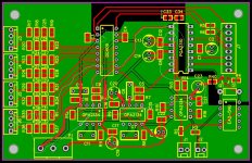
So I've rebuilt PCB a little following the recommendations. I got rid of ESD protection diodes, filters are now completely SMD with C0G capacitors instead of a film, replaced tantalum capacitors with aluminium electrolytics. Also I've laid out digital part so the entire PCB is kinda finished now.
Below I've attached complete proper schematics and PCB layout.
Below I've attached complete proper schematics and PCB layout.
Attachments
Improved design looks good,
I have identified a few things you might want to look at.
I dont know if you had a design rule checker on your PCB package but it looks like the diagonal tracks exiting r1 r31 r21 r22 are too close to the pad and you might get etching or solder wisker problems.
The digital and analogue grounds do not appear to be connected they need to be connected together somewhere or they can float from each other causing problems.
The digital control lines going to the mux can be a source of noise from the microcontroller, an in line resistor and capacitor helps to filter this off. It should be filtered to the analogue ground but preferable close to the ground plane split.
belyakove
I would like to know if you already have the microcontroller control code for this design and also know if you will share it with us.
Your PCB is really nice now.
Regards
Ronaldo
I do have code for microcontroller. I'm using Arduino Nano to control the preamp. For now the code is not completely finished.
You can see the source code in attachment.
Things already covered:
- LCD (It is hooked up via shift register 74HC595 to save available pins on Arduino. It is controlled via SPI)
- PGA2310 control
- DG409 (input switch) control
- Turning on/off of analog power supply (I'm going be using PhotoMOS relay for it but you can hook it up to regular relay driving circuit)
- Turn on/off Mute
- IR control
- Saving of current settings to energy independent memory (EEPROM)
Things to be covered:
- Volume control rotary encoder
- Input switch rotary encoder (to control amp without IR remote)
- Switching on/off display light
- DAC controlling
Improved design looks good,
I have identified a few things you might want to look at.
I dont know if you had a design rule checker on your PCB package but it looks like the diagonal tracks exiting r1 r31 r21 r22 are too close to the pad and you might get etching or solder wisker problems.
The digital and analogue grounds do not appear to be connected they need to be connected together somewhere or they can float from each other causing problems.
The digital control lines going to the mux can be a source of noise from the microcontroller, an in line resistor and capacitor helps to filter this off. It should be filtered to the analogue ground but preferable close to the ground plane split.
I'm going to order manufacturing of PCB from EasyEDA service so I didn't think this kind of routing (r1, r31, etc) will be a problem because as I understand traces will be covered with solder mask. However it's not a problem at all to alter that tracks a little.
Analog and digital grounds are indeed not connected on this board. I was planning to connect them outside the board. Actually I'm planning to put DAC board in the same enclosure and power it up from the same power supply. There is a connection of digital and analog grounds on DAC board next to the DAC chip as required for this kind of chips. I thought this connection will be sufficient and will allow me to avoid ground loop. However I might be wrong here.
As for mux lines. I was wondering what 22k resistors are doing on these lines in A32 amp. Now it starts to make sense. Do I understand correctly that resistor should be inline but capacitor should be connected between mux line and analog ground? If capacitor will be connected inline I think it will just block the signal to the mux as it is DC and mux won't work.
Do I understand correctly that extending analog ground plane under mux lines would help as it forms a capacitor between mux line and ground plane, however since my PCB is only 2 layer (unlike 4 layer Arcam's PCB. I don't see capacitor there, only resistor) there will be quite big distance between mux line and ground place and it will be ineffective?
And thank you very much for your help!
Attachments
Last edited:
You will probably get away with the tracks they are just quite close and I dint know the tolerance of the pcb fab you are planning to use. If you have solder mask you are right this eliminates the risk of solder wiskers.
You are correct the capacitor goes to the ground plane not in series. 22k is very high and was the highest we could get away with for reliable operation you might need to experiment abit if you decide to fit these as depending on the drive strength of your microcontroller it might need to be a smaller resistor. A capacitor of 10pF to 100pF will form a good filter with a resistor of 10k or up the exact value is not that critical but again you sometimes find a sweet spot by trial end error. Extending the ground would help a little as well.
Grounding is very complex for circuits like this as you have so many parts that have both digital and analogue connection but you are right under the DAC is a good starting point. Remeber all the current that goes into an analogue device from the digital side has to return all the way to where it came from via the ground plane and via either the link between the planes or for high speed signals via a capacitive coupling between planes.
I read in TI's book "Op Amps for Everyone" the following statement "Digital signals must be routed around analog circuitry, and not overlap analog ground and power planes." That's why actually I laid out mux traces in such a way that analog ground plane is not under them. But what you recommend is actually to ac couple mux lines to analog ground plane using capacitor. Can you please explain how it works?
Stop using ceramic caps in the analog portion of any audio component, even in DC servos.
Refer to following article for the reasons why not.
Picking Capacitors - Walter G. Jung and Richard Marsh
Without spending silly money for film caps Wima and others make some very nice polypropylene 63 and 100 VDC caps with fairly small foot prints. I genenerally use MIT and Relcap , both used by Constellation Audio, John Curl, and Pass labs for critical functions like RIAA filters. But they are big and expensive. Pass seems to also like Panasonic polypropelene for less critical functions.
Last edited:
This is a bit of a simplification. What you want is to avoid the currect from the digital signals causing voltage variation in the analogue ground plane.
However the current is going to return somehow, so sometimes its better to guide it back via low impedance capacitive paths rather than let it find its own way.
It is very very difficult to predict what will perform best so I often allow many options then test to see which one works best.
However the current is going to return somehow, so sometimes its better to guide it back via low impedance capacitive paths rather than let it find its own way.
It is very very difficult to predict what will perform best so I often allow many options then test to see which one works best.
Stop using ceramic caps in the analog portion of any audio component, even in DC servos.
Refer to following article for the reasons why not.
Picking Capacitors - Walter G. Jung and Richard Marsh
While this is a good article, note that 'ceramic' caps are not all one thing. X7R, X5R, and Z5U caps are very nonlinear, but modern C0G/NP0 dielectric capacitors use a Calcium Zirconate dielectric with nickel electrodes, and they perform extremely well, often measurably better than film caps with less than perfect end terminations. In 1980 when this paper was written, C0G caps often used precious metal electrodes and a different dielectric chemistry, and much has improved since them. Now, it is very difficult to buy a C0G cap with anything but a Calcium Zirconate dielectric - a good thing.
I have personally tested 2nd harmonic distortion of 50 and 100V Murata 0.1µF 3216 size C0G MLCC caps, comparing them under varying DC bias to Component Research 200V 0.1µF foil Teflon caps, and despite their extremely small relative size, the C0G dielectric starts to become nonlinear at only about 3x less total dielectric voltage (10dB earlier) than the Teflon units. The test instrument distortion floor for this test is around -145dBV, with drive levels causing distortion at around +10dBV. This is extremely low distortion.
Traditional film caps often exhibit more distortion due to poor quality end terminations (how well the sputtered film or foil connects to the lead wires), and not dielectric saturation, but because of the way that they are manufactured, this must be screened for individually. A MLCC will not suffer from this problem, so every unit will perform consistently well. Further, the magnitude of distortion from this mechanism can be much higher than that of the dielectric saturation, so unless you can screen each cap, film caps are actually much riskier than a quality C0G MLCC.
Bruce Hofer from Audio Precision gave a series of presentations around 2015, and the attachment is an interesting slide from this presentation. It shows the relative 2nd and 3rd harmonic distortion performance of a polypropylene film-foil cap, used in their generator or analyzer, with a composite of multiple NP0 MLCC caps. You can see the lower overall distortion of the C0G as well as the very small variance. The film caps, presumably due to end termination problems, had a distortion variance of 10dB, with the poor performers being >30dB worse than pretty much every MLCC.
My tests of the C0G caps more or less agree with these numbers, but I was comparing MLCCs to a hermetically sealed Component Research cap, which are designed not to have end termination problems, and performed much better than the FPP caps that Audiio Precision was using. However, if you aren't buying space grade hermetically sealed caps, expect randomly awful behavior from some film units.
Attachments

:thumbs up for MLCC. my rule is only use NPO/COG in the signal path and for RF, for supply decoupling, use X7R MLCC. It was now 20 years ago we were told to stop designing in tantalum and use MLCC, due cost cost, reliability, performance. cost break points was around 10uF to switch over to electrolytic, but avoid electrolytic if you can.
As for the grounding, since you are not sure, try to design so that you have options to try during testing. have a way to short the planes together under the analog/digital separation as TI did it in their PGA23xx app notes/dev pcb.
if you try the above, experiment with,
try a small R, a ferrite bead or even a cap to test what is the best method to couple the planes. you can even try to connect the returns at the PS.
some of this depends on the PS design.
I've added filtering resistors and capacitors to DG409 digital lines and also added optional R40 0 ohm resistor coupling ground planes. Also placed mounting holes. Here's an updated schematic and layout version.
Attachments
Complete Pre-Amplifier Project?
It is becoming more and more interesting.
I would like to send you some ideas to you think about:
1- The servo control amplifier cold be 2nd order filter to have a better low frequency corner cut off and impact in low frequency limit of audio signal;
2- Add a small resistor in parallel with C3 an C10 to generate a better start up behavior.
3- Change the Mute relay arrangement to avoid operational amplifier output short circuit during start-up. I believe it will give more long life to operational amplifier as it avoid start-up stress.
Another question concerning microcontroller board - do you have schematics of it now and you could also share it with us?
I am not familiar with Arduino, so I ask you the hex file to program a chip as I have ELNEC universal programmer in my laboratory.
I got some samples of PGA2310 and PGA2311 from TI some time ago, so I see here a good chance to try it.
Regards
Ronaldo
HI,
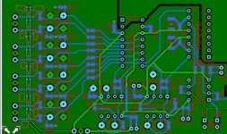
I have made a few suggestions on your layout. I used paint so it is very rough and ready.
The white line shows an example of how the current for one of the signals might flow. As it meets each active device return current will flow from the ground pin of the device. Note the analogue mux is a resistive switch and is not active so very little if any return current will flow from this. Note how complex the return paths are due to the ground plane cuts. (If you review this for each of the different inputs you will see the value of a really good ground plane.
In red I have suggested some improvements; by moving tracks to the top layer you can significantly improve the ground plane. if you do the return path analysis for all the other signals you will probably find other paths you would like to optimise.
As one of your return paths is round the top of the chip, I would recommend making this a bit wider I suspect the crosstalk from the digital track will be much less significant than this high impedance return.
I haven't shown it but it would be preferable to create a larger via for changing sides when tracking the power supplies as tiny vias can be quite resistive and inductive.
If you sign up to this PCB manufacturers site (it free) you can upload your gerbers and they will do a free online DFM (Design for Manufacture test) this will let you know if there are any problems with your gerbers. I now use this for all my PCBs if I am going to buy them from them or not as it is such a useful service. (They are not that cheap compared to the Chinese manufacturers but at work often time is more important than the cost)
Eurocircuits :: Services
Attachments
- Status
- This old topic is closed. If you want to reopen this topic, contact a moderator using the "Report Post" button.
- Home
- Source & Line
- Analog Line Level
- Laying out preamp pcb