
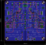
Hi Marc you may wanna have a closer look at your KAS1381 pin out, from what I can tell, the KAS1381 on your schematic is an NPN when it should really be a PNP.I have received the PCB today and they look nice")
I could be wrong as my vision is not 2020.Hi EmeryBB,
Your vision is quite good and you are right, I made a mistake by putting an NPN instead of a PNP transistor on the schematic
These transistors make me crazy, only 3 pins and plenty of possibility to make a mistake
As a result I will have to cross emitter and collector legs, the pinout is ECB, it is OK as XRK say, but the schematic was wrong !
Thanks to let me know that before I solder them
I enclosed the corrected schema and PCB of the first version but this modification must be done also for the last version of course...
Best regards,
Marc
Attachments
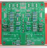
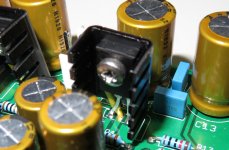
The AKSA-Lender preamplifier is assembled (one 33 pF cap missing !) and the legs are crossed (see pictures)
Next step : testing
Rgds,
Marc
Next step : testing
Rgds,
Marc
Attachments
Hi,
Not yet started test, too busy
zman01,
It is a compact PCB (10 cm x 10 cm) and big capacitors from Wima 41.5 x 17 x 29 mm ( https://www.mouser.fr/ProductDetail...dA3IHMKc%2BZFZbral7%2BzDXWUA0GoeuWPycvixH9odi ). There is an other possibility by Vishay ( https://www.mouser.fr/ProductDetail...jsyv8wssl0QBtRu1jexptDZWL2v8fWt1TAICVo7zQcQ== )... There are more options with bigger capacitors like Mundorf ( Mundorf MCap-250 10uF :: M-Cap Series :: Mundorf :: Film Foil :: Capacitors :: Passive Components :: Electronic Parts :: Banzai Music GmbH ), some version will not fit in the PCB
Rgds,
Marc
The Mundorf M Caps (alum in oil) are nice. Recently I have tried metallized paper safety caps for bypass and they sound nice too with larger electrolytic like Silmic II. Also, metallized polycarbonate are nice too.
Please can you post the exactly type (Mundorf)that will be fιt well?
Waiting for some milf resistors.
Mundorf MCap EVO Oil - Willys-Hifi LtdPlease can you post the exactly type (Mundorf)that will be fιt well?
Waiting for some milf resistors.
Thanks Hicoco!
Finally running with PCA daughter boards
I got my Aksa Lender working for the first time in August 2018. It was not an easy build for me at the time and I made a number of mistakes, but with X’s ever present helping hand I got it debugged and singing. The Lender immediately dethroned my beloved B1 and brought a new sparkle, much better bass and dynamic to my ACA amp. This is an amazing sounding preamp.
I seem to have an affinity for the BF862 jfets, since I used them in my B1 (i.s.o. 2SK170’s), almost used them in my ACA and I have built X’s Pocket Class A (PCA) headamp using BF862’s. Despite being a fantastic sounding headamp, the PCA also sounds amazing as a preamp.
One fine day in June last year I just had this crazy thought – I wonder if the PCA topology can be used as a different version for the Lender preamp? X liked the idea and within a few hours the schematic was drawn, simmed and the layout was done overnight by JPS. By July X built and tested the first PCA boards for the Lender, and I subsequently ordered boards on the XRKAudio Etsy shop.
I took a long time before populating my PCA boards. I again used BF862’s (now out of production too) for my build, but in the process of adjusting the rail voltage somehow the DC step-up went up in smoke and I shelved it.
Very happy to report that finally my Lender is now running with the PCA (BF862) boards. Rail voltage set to the sweet spot (for BF862) of 18.2V, my Lender is singing again. Not sure if it can be called a Lender anymore since it’s a different topology now, but it (still) sounds stunning. Cannot believe I lived so many months without it. Does the PCA version sound better/different to the original version? I simply can’t answer that. They both sound stunning. Member Skylar88 and I might compare (A/B test) the two versions one day.
I also upgraded my Aksa Lender with a cheap IR remote volume control and what a pleasure to not have to jump up (at my age) between tracks to adjust the volume. I am now an even happier Aksa Lender preamp owner!
Btw, there is renewed interest and new developments of the PCA headamp (one of the highlights of my diy journey and sparked the PCA boards) – see here: Hakuin SE Class A HP Amp
I got my Aksa Lender working for the first time in August 2018. It was not an easy build for me at the time and I made a number of mistakes, but with X’s ever present helping hand I got it debugged and singing. The Lender immediately dethroned my beloved B1 and brought a new sparkle, much better bass and dynamic to my ACA amp. This is an amazing sounding preamp.
I seem to have an affinity for the BF862 jfets, since I used them in my B1 (i.s.o. 2SK170’s), almost used them in my ACA and I have built X’s Pocket Class A (PCA) headamp using BF862’s. Despite being a fantastic sounding headamp, the PCA also sounds amazing as a preamp.
One fine day in June last year I just had this crazy thought – I wonder if the PCA topology can be used as a different version for the Lender preamp? X liked the idea and within a few hours the schematic was drawn, simmed and the layout was done overnight by JPS. By July X built and tested the first PCA boards for the Lender, and I subsequently ordered boards on the XRKAudio Etsy shop.
I took a long time before populating my PCA boards. I again used BF862’s (now out of production too) for my build, but in the process of adjusting the rail voltage somehow the DC step-up went up in smoke and I shelved it.
Very happy to report that finally my Lender is now running with the PCA (BF862) boards. Rail voltage set to the sweet spot (for BF862) of 18.2V, my Lender is singing again. Not sure if it can be called a Lender anymore since it’s a different topology now, but it (still) sounds stunning. Cannot believe I lived so many months without it. Does the PCA version sound better/different to the original version? I simply can’t answer that. They both sound stunning. Member Skylar88 and I might compare (A/B test) the two versions one day.I also upgraded my Aksa Lender with a cheap IR remote volume control and what a pleasure to not have to jump up (at my age) between tracks to adjust the volume. I am now an even happier Aksa Lender preamp owner!
Btw, there is renewed interest and new developments of the PCA headamp (one of the highlights of my diy journey and sparked the PCA boards) – see here: Hakuin SE Class A HP Amp
Hi Twocents,
Great to hear that your preamp is back in action again with the PCA daughterboards! Congrats!
I know what you mean about the volume remote. I have an SMSL Sanskrit 10 DAC and it comes with an IR remote control for volume and mute function. I find myself using all the time now. Not sure my preamp even needs a volume pot of this DAC is the source.
Glad to hear of the interest in the Hakuin amplifier. You will be happy to hear that the Hakuin has been made into a daughterboard for the Yarra. It can use 2SK209, or 2SK170’s, or even BF862’s. The diehard will use a Toshiba 2SA1837 for the output BJT.
Hello everyone!
I’ve started to gather parts to assemble the Lender to drive the Mofo amplifier to clipping or very close to it.
I have a few question regarding the BoM for the MB and for the SMT modules. Hopefully you can help me to clarify some questions...
MB BoM :
C127/137 and C1027/1037, are those in parallel (like bypass) since they have different values (1uF vs .1uF)?
For C1022/1032, C1023/1033, C123/133, C122/132, my guess is if you use C1022/1032 you bypass it with C1023/1033 ? Or you use either C122/132, C123/133 instead @ 10uF ?
- I was wondering if using 4.7uF would be sufficient for C122 or C123? Lower value?
SMT PCB Gain resistors :
The default gain for the SMT BoM is what exactly? I want to make sure I'm set properly to drive that Mofo to clipping or very close to it.
X told me that the BoM default gain is 11 and suggested to use 15k for R113 and 680R for R112 for 27.2dB gain (23x) for optimal gain for Mofo.
For power, I was thinking of a PoE injector SMPS which usually is 48Vdc to 52Vdc instead of DC/DC boost?
I know it is many questions but I prefer the measure twice cut once approach! Hehe
Thanks
Do
Hi Do,
Very good preamp choice to drive your MoFo, it’s a wonderful combination
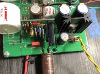
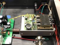
Here’s a few of my thoughts about my ALP build.
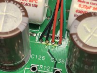
-C127/C1027 is a bypass location for the C126 electrolytic cap, pick either a box type or your favorite film cap for this location.
- For the input capacitor there are many options here, use one, either a box type or your favorite film cap with a value not lower than 4.7µF.
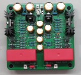
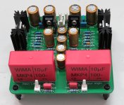
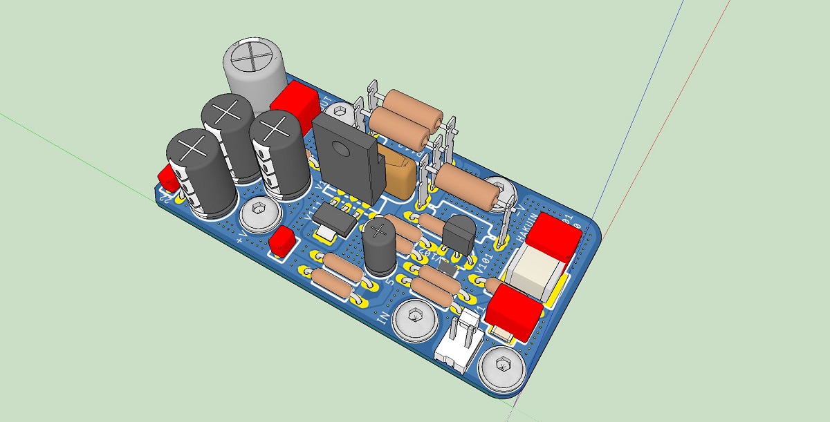
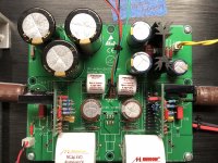
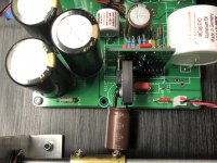
-Take a peek at my attached pictures to see how C124/C134 are positioned to allow room for the daughterboard heatsinks. Driving a MoFo at approximately 48-50vdc the sinks get very warm if not hot.
-I preferred a regulated linear PSU, the SMPS route was introducing noise in my system. Try a Bel or Power One regulated PSU, you can pick them up pretty cheap new or used. The HB48-0.5-AG has 10% adjustability via a trimpot so feeding regulated 52vdc gets you approximately 49vdc after the onboard capMX. This is the supply I use with my Big MoFo amp.
I’m currently using a 24vdc version of this power supply with my PCA daughter boards.
-R141 use 10K resistor
-V141 use standard 1N00x diode
Looking forward to following your ALP build journey
Cheers,
Vunce
Very good preamp choice to drive your MoFo, it’s a wonderful combination
Here’s a few of my thoughts about my ALP build.
-C127/C1027 is a bypass location for the C126 electrolytic cap, pick either a box type or your favorite film cap for this location.
- For the input capacitor there are many options here, use one, either a box type or your favorite film cap with a value not lower than 4.7µF.
-Take a peek at my attached pictures to see how C124/C134 are positioned to allow room for the daughterboard heatsinks. Driving a MoFo at approximately 48-50vdc the sinks get very warm if not hot.
-I preferred a regulated linear PSU, the SMPS route was introducing noise in my system. Try a Bel or Power One regulated PSU, you can pick them up pretty cheap new or used. The HB48-0.5-AG has 10% adjustability via a trimpot so feeding regulated 52vdc gets you approximately 49vdc after the onboard capMX. This is the supply I use with my Big MoFo amp.
I’m currently using a 24vdc version of this power supply with my PCA daughter boards.
-R141 use 10K resistor
-V141 use standard 1N00x diode
Looking forward to following your ALP build journey
Cheers,
Vunce
Attachments
-
 212597A9-DB4B-4AE9-B003-32A6583BE1CB.jpg1 MB · Views: 288
 -
 5D8975BC-E91D-4873-BF3F-18AD3148708C.jpg962.4 KB · Views: 291
 -
 F5D0D5D4-FBB4-4A38-BF26-7995A7CD7E37.jpg1,011.6 KB · Views: 296
 -
 49444500-EBE5-4FFE-A8AD-6B3CDDF829C1.jpg1,003 KB · Views: 281
 -
 71565878-2175-4F0B-AE41-7B05CBBBFF08.jpg1,008.3 KB · Views: 150
 -
 B57BBFFB-D3BC-407B-9E75-FD5CF35D4B37.jpg580.8 KB · Views: 138
Last edited:
- Home
- Source & Line
- Analog Line Level
- AKSA's Lender Preamp with 40Vpp Output