This transformer I've used seems to be real crappy and inefficient. The laminations are 0.5mm thick, thus eddy current loss must be high.The windings are probably very thin too, resulting in excessive I²R loss as well.
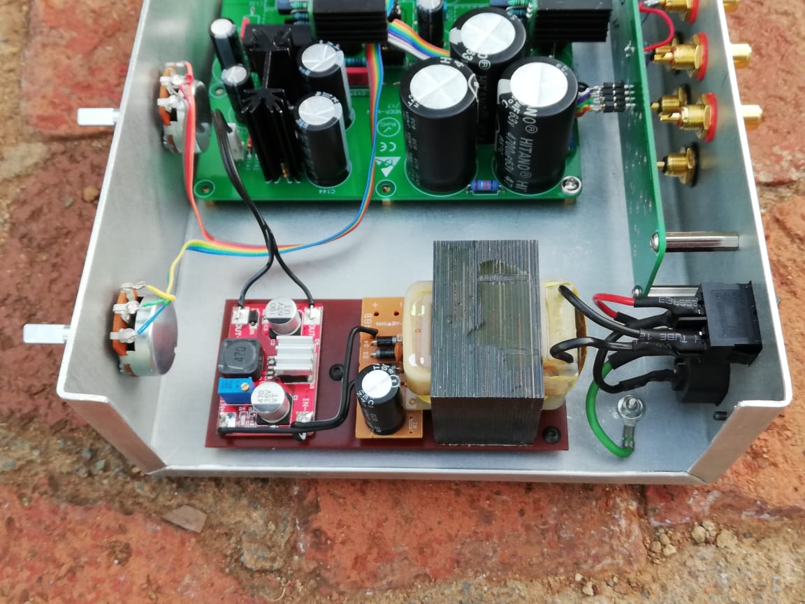
My AKSA Lender pre chassis is not ventilated, and it runs as hot as an ACA. I've sent the lid in for laser cut ventilation slots, but maybe I should get rid of the heat source anyway.
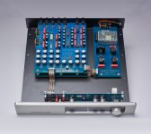
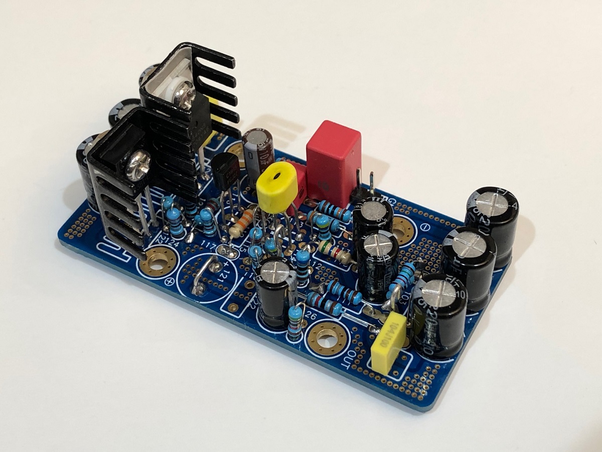
I'm considering to rather us an internal SMPS, like in the Sutherland N1 preamp pictured below. My question is: (for sizing the SMPS) What would the current draw be on the AKSA Lender (15dB version)? ...and if I measure it, would the current draw vary with sound volume? i.e. should I measure at high level?
Does that look like a Cap Mx on the N1 Sutherland PSU board?
My AKSA Lender pre chassis is not ventilated, and it runs as hot as an ACA. I've sent the lid in for laser cut ventilation slots, but maybe I should get rid of the heat source anyway.
I'm considering to rather us an internal SMPS, like in the Sutherland N1 preamp pictured below. My question is: (for sizing the SMPS) What would the current draw be on the AKSA Lender (15dB version)? ...and if I measure it, would the current draw vary with sound volume? i.e. should I measure at high level?
Does that look like a Cap Mx on the N1 Sutherland PSU board?
Attachments
Last edited:
Hi Skylar,
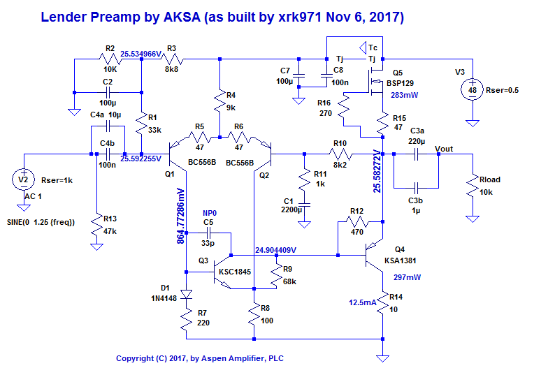
The Aksa Lender Preamp runs at about 15mA to 17mA bias current in stock form. So dissipation across the DN2540 and 2SA1837 equals 48v x 0.017A x 2 ch = 1.6w. The cap Mx is 4v x 0.017A x 2 = 0.14w. The DC-DC step up is about 90% efficient and assuming it uses a MOSFET with 4v drop, again another 0.14w. So about 2w total. Your little transformer may be adding a couple more watts. Maybe 4w total which can get warm if not heatsink or vented. Some air slots at the top and bottom should help cooking it off, or try using an external wall wart Class 2 transformer. I don’t recommend bypassing the cap multiplier. Besides filtering ripple it gives a slow start ramp up to prevent thump. Meanwells may work - that unit looks like it might be noisy. Also the DC-DC you have is noisier than the white aluminum ones I recommended.
What value source resistor are you using after the DN2540? If you are using lower than 47ohm there your heat output will be significantly higher. Remember that for headphone use, the current is higher but Vcc dropped to 24v. 48v at 75mA would be a lot of heat (7w a pair from DBs alone).
I just ordered the M2X Melbourne DB PCBs. They might make useful standalone preamps and can be DC coupled on output. Just need fairly clean +/-24v supplies.
Last edited:
What value source resistor are you using after the DN2540? If you are using lower than 47ohm there your heat output will be significantly higher. Remember that for headphone use, the current is higher but Vcc dropped to 24v. 48v at 75mA would be a lot of heat (7w a pair from DBs alone).
Thanks X.
R11 = 2K2 for 15dB gain, as per your advice.
I’ll wait for the chassis to come back from the engineering shop and see if the ventilation slots make a difference. If that doesn't solve the heat problem, I’ll try a 15W Meanwell (RS-15-24) that is currently being used for the B1.
I'll also try to get the lower noise white DC-DC converter at some point.
Hi Skylar,
Any luck with getting the preamp case to run cooler? I was actually asking about the bias current setting resistor R15 (in schematic below) that is at the source of the depletion mode DN2540. Default is 47R which gives about 16mA bias current. On the headphone amp, the Vcc is set much lower at 24v and the bias much higher (about 80mA). Running 80mA at 48v would indeed be very hot - you would burn your finger if you touched the heatsinks on the DN2540 or 2SA1837.
Any luck with getting the preamp case to run cooler? I was actually asking about the bias current setting resistor R15 (in schematic below) that is at the source of the depletion mode DN2540. Default is 47R which gives about 16mA bias current. On the headphone amp, the Vcc is set much lower at 24v and the bias much higher (about 80mA). Running 80mA at 48v would indeed be very hot - you would burn your finger if you touched the heatsinks on the DN2540 or 2SA1837.
Hi Skylar,
Any luck with getting the preamp case to run cooler? I was actually asking about the bias current setting resistor R15 (in schematic below) that is at the source of the depletion mode DN2540. Default is 47R which gives about 16mA bias current. On the headphone amp, the Vcc is set much lower at 24v and the bias much higher (about 80mA). Running 80mA at 48v would indeed be very hot - you would burn your finger if you touched the heatsinks on the DN2540 or 2SA1837.
Hi X,
R15 is the 'standard' 47R5 and the heatsinks don't get very hot. Although it's running at 48V, I can keep my finger on the sinks indefinitely. It's the PSU transformer that makes the most heat.
I'm still waiting for the chassis parts to come back from the engineering shop, but I'm hoping the ventilation slots will make a big difference. If it doesn't, I'll shoehorn a 15W Meanwell in there.
Received my boards thanks XRK, they look great but bigger than anticipated (should have measured them I guess, rather than 'yeah that should fit ok' ") )
)
My plan is to run this as a front end to an ACA or possibly MoFo, do you see any issue in pulling 24v from the power amp and just mounting the DC-DC step up in the pre amp case (I don't see a problem). My only other thought would be any suggestion for a nice connector for the DC (I cannot really think beyond the 2.5mm DC barrel plugs used for 24v in on the ACA). I'm really looking to avoid excessive external PSUs.
)My plan is to run this as a front end to an ACA or possibly MoFo, do you see any issue in pulling 24v from the power amp and just mounting the DC-DC step up in the pre amp case (I don't see a problem). My only other thought would be any suggestion for a nice connector for the DC (I cannot really think beyond the 2.5mm DC barrel plugs used for 24v in on the ACA). I'm really looking to avoid excessive external PSUs.
Received my boards thanks XRK, they look great but bigger than anticipated (should have measured them I guess, rather than 'yeah that should fit ok'
My plan is to run this as a front end to an ACA or possibly MoFo, do you see any issue in pulling 24v from the power amp and just mounting the DC-DC step up in the pre amp case (I don't see a problem). My only other thought would be any suggestion for a nice connector for the DC (I cannot really think beyond the 2.5mm DC barrel plugs used for 24v in on the ACA). I'm really looking to avoid excessive external PSUs.
Sounds like a good plan. The 5.5mm dis barrel jacks are what I would use too.
Right, I want a remote volume on this (I'd also like some automated source switching), I plan to control it with a tiny arduino type microcontroller board that 'sees' my samsung telly remote. would people suggest:
1) the pot needs a coupling shaft, drive this with a separate motor and slipper clutch assembly lashed up, off to one side of the pcb.
2) Use an alps RK27 motorised pot and wire it to the PCB points.
3) Use a separate encoder and relay ladder type of volume control. Suggestions on something to use please.
The source switching can be as simple as I have 2 main sources, the toslink/SPDiF from the telly and the analogue from my RPi streamer. If I get a SPDiF signal locked then switch to that input, if the telly is off and no SPDiF switch to the first analogue inputs for the streamer. I may have more analogue ins and just have a selector that goes:
Auto switch between 1 and 2
Input 1
Input 2
Input 3
Help please! I'm rather short on space too
Hi Puggie
I'd say, keep it simple and adjust volume on the source (which probably has remote volume control already) - not on the preamp. The times that I had to adjust volume on the pre can be counted on one hand. The main reason that I built my AKSA Lender pre with a pot for each channel was for balance control.
The same goes for input selection. Why complicate matters? ...unless you get enjoyment (and bragging rights) out of designing and putting together complicated MCU gadgets.
The main source has digital output so I cannot alter volume at source.
The main point of a pre-amp in my setup will be system integration. I have 2 main sources possibly expanding to 3 or 4:
1) TV which is modern so has no analogue outputs at all (stupid IMHO) so optical SPDiF out into a DAC (which I hope to drop in the same case as the pre-amp)
2) RPi based streamer which is currently using an Allo Boss 1.2, may go katana, may go digione and run into a DAC like the TV.
3) May get a record deck again, would drop the phono stage in the plinth if I do
4) Always nice to have a spare
I have a TV that has one remote and dreadful speakers, my aim here is to have one system with a pair of speakers and amp, I can amplify the TV or RPi streamer though the one pre-amp > Power amp setup and drive it all from one remote control (I need everyone from the 2 year old to the mother in law to be able to operate this without bothering me) it must be simple and intuitive. Operating the volume of each device from its own remote and individual volume is IMHO not simple intuitive or elegant. I need one system that does is all I'm afraid.
EDIT: That sounds quite dismissive and I see your point entirely. if I had the space for a dedicated HiFi for music then I would be running a much simpler set up, probably the RPi with digital volume control running into the AKSA pre amp with a single dedicated input to the power amp. Hell I'd probably have put the RPi and pre amp all in one box just feeding the power amp the one stereo signal and power.
The main point of a pre-amp in my setup will be system integration. I have 2 main sources possibly expanding to 3 or 4:
1) TV which is modern so has no analogue outputs at all (stupid IMHO) so optical SPDiF out into a DAC (which I hope to drop in the same case as the pre-amp)
2) RPi based streamer which is currently using an Allo Boss 1.2, may go katana, may go digione and run into a DAC like the TV.
3) May get a record deck again, would drop the phono stage in the plinth if I do
4) Always nice to have a spare
I have a TV that has one remote and dreadful speakers, my aim here is to have one system with a pair of speakers and amp, I can amplify the TV or RPi streamer though the one pre-amp > Power amp setup and drive it all from one remote control (I need everyone from the 2 year old to the mother in law to be able to operate this without bothering me
) it must be simple and intuitive. Operating the volume of each device from its own remote and individual volume is IMHO not simple intuitive or elegant. I need one system that does is all I'm afraid.EDIT: That sounds quite dismissive and I see your point entirely. if I had the space for a dedicated HiFi for music then I would be running a much simpler set up, probably the RPi with digital volume control running into the AKSA pre amp with a single dedicated input to the power amp. Hell I'd probably have put the RPi and pre amp all in one box just feeding the power amp the one stereo signal and power.
Last edited:
Question....The link you have posted for the BOM will not work. Also where can I get a schematic and BOM for the Aksa Preamp? I can purchase the boards from Etsy, but they have no support. Thanks
The support is always there if you asked - or you can ask here on the forums like you are doing now. Have you checked the first post of the GB thread for this Preamp? I think you will find most of what you need. I generally respond within the same day for Etsy site questions.
AKSA's Lender Preamp with 40Vpp Ouput GB
JPS64 and I just made a dual rail version of the Aksa Lender Preamp for use as a front end in the M2X amp. It actually can be used as a standalone preamp and it has a built in CRCRC power supply and input and output coupling caps. You would need to feed it fairly quiet dual rail from say */-15v to +/-27v and it can work. It has the option of running without an output coupling cap as it has circa 0v output offset. There is also a mu-follower on the output for lower distortion but overall H2 and H3 are closer together.
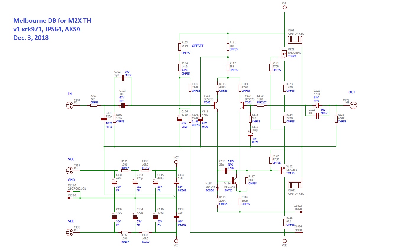
A main board to hold this and provide a cap filtered dual rail from a DC-DC converter would be nice.
A main board to hold this and provide a cap filtered dual rail from a DC-DC converter would be nice.
Hey, all the help and support you would need is available right here as X said - that is how I managed to build and de-bug mine. This preamp is a winner and really cheap to build. Hope you give it a try. The Etsy shop works great too.Question....The link you have posted for the BOM will not work. Also where can I get a schematic and BOM for the Aksa Preamp? I can purchase the boards from Etsy, but they have no support. Thanks
The link on post 1 of the GB thread works fine and gives a very complete BOM.
Just received my set of boards. Plan is to use this as a front end for the ACA ver 1.6 . Some very basic questions, no laughing please (at least not out loud )
Are there recommended parts lists for the input selector, power switch and CLC?
Am I right in that the input selector board also has 2 outputs so you could run a main amp plus subwoofer?
For use with the ACA the only recommended change is to use 2.2k for r11 correct?
I also purchased a DC step up board and would like to run the preamp off the same SMPS used for the ACA, do I just set it to 40v or should I be targeting some other value?
)Are there recommended parts lists for the input selector, power switch and CLC?
Am I right in that the input selector board also has 2 outputs so you could run a main amp plus subwoofer?
For use with the ACA the only recommended change is to use 2.2k for r11 correct?
I also purchased a DC step up board and would like to run the preamp off the same SMPS used for the ACA, do I just set it to 40v or should I be targeting some other value?
Just received my set of boards. Plan is to use this as a front end for the ACA ver 1.6 . Some very basic questions, no laughing please (at least not out loud
Are there recommended parts lists for the input selector, power switch and CLC?
Am I right in that the input selector board also has 2 outputs so you could run a main amp plus subwoofer?
For use with the ACA the only recommended change is to use 2.2k for r11 correct?
I also purchased a DC step up board and would like to run the preamp off the same SMPS used for the ACA, do I just set it to 40v or should I be targeting some other value?
For input selector switch, the Lorlin 4 position 3 Pole rotary switch works best. RS #665-203. Make sure to get the through hole variant.
The input selector board only has one output and four inputs. The way the board is designed also had me thinking there are two outputs. The RCA pair closest to the the switch is the output.
Correct, 2k2 for R11 gives about 15dB gain. That's what I'm using with my ACA.
- Home
- Source & Line
- Analog Line Level
- AKSA's Lender Preamp with 40Vpp Output