
I listened to this preamp for a few songs. Very very nice. Great to have a unified PSU cap Mx. I really like the swappable amp core modules. This will lead to some experimenting for sure. Headphone amp version is but a swap away (don’t forget to drop Vcc). That huge heatsink on the cap Mx is not even warm when running as a preamp. But will get warm when running as a headphone amp with more bias current. It’s well sized (probably over sized) though.
Looking forward to using this with input selector and real case. It’s a very easy amp to build if you have the right MELF parts (or wait for the 0805/1206 chip version). The TH board was a no brainer. They can be assembled in under an hour.
Looking forward to using this with input selector and real case. It’s a very easy amp to build if you have the right MELF parts (or wait for the 0805/1206 chip version). The TH board was a no brainer. They can be assembled in under an hour.
Last edited:
Star Ground Plane
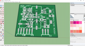
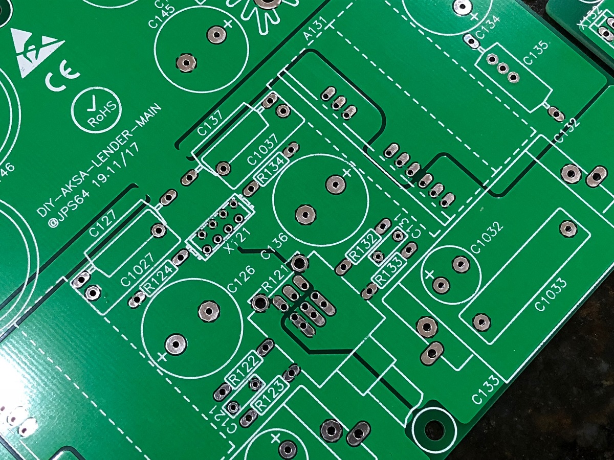
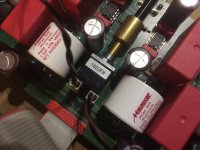
So I was looking more carefully at the layout now that I have it in my hands and hear how good and low noise it sounds. Look carefully at the top side of the PCB and notice the well-orchestrated cuts in it that divide the various sections of the amplifier: cap Mx/CRCRC, left PSU, right PSU, left analog, right analog (down to the split at the dual-gang volume pot pins), and the branches all originate from the centrally mounted star point X121 connector. Just wanted to give my hats off to JPS64 for such an elegant and well-thought out design. I have never seen such a nice star ground plane implemented in DIY before. I asked JP how he designs the ground plane, he said "You have to think like an electron!" Indeed.")
Well, it's working out very nicely.
So I was looking more carefully at the layout now that I have it in my hands and hear how good and low noise it sounds. Look carefully at the top side of the PCB and notice the well-orchestrated cuts in it that divide the various sections of the amplifier: cap Mx/CRCRC, left PSU, right PSU, left analog, right analog (down to the split at the dual-gang volume pot pins), and the branches all originate from the centrally mounted star point X121 connector. Just wanted to give my hats off to JPS64 for such an elegant and well-thought out design. I have never seen such a nice star ground plane implemented in DIY before. I asked JP how he designs the ground plane, he said "You have to think like an electron!" Indeed.
Well, it's working out very nicely.
Looking to source the right rotary selector switch. Looking at 2 different options right now. Any reason either of these would NOT work?
ITT Cannon C&K A30403RNCBE A Series 3 Pole 4 Position Rotary Switch
ITT Cannon C&K A30403RNCBE A Series 3 Pole 4 Position Rotary Switch 30 Deg 2 pcs | eBay
OR
Lorlin CK1031
CK1031 Lorlin | Mouser
ITT Cannon C&K A30403RNCBE A Series 3 Pole 4 Position Rotary Switch
ITT Cannon C&K A30403RNCBE A Series 3 Pole 4 Position Rotary Switch 30 Deg 2 pcs | eBay
OR
Lorlin CK1031
CK1031 Lorlin | Mouser
Lorlin CK1031 is solder tag not PCB.
You need: CK1051 or CK1500 or CK1952 --> CK1952 is gold plated; CK1051 should be available (RS, CONRAD, ebay).
Buy this one: A30442MNCBE C&K Components | Mouser Deutschland
JP
You need: CK1051 or CK1500 or CK1952 --> CK1952 is gold plated; CK1051 should be available (RS, CONRAD, ebay).
Buy this one: A30442MNCBE C&K Components | Mouser Deutschland
JP
Thanks JSP. Scored some CK1051's on eBay. I think there are a few left if anyone is interested.
3x4 rotary switch 3-pole 4-position PCB mount (DS3PC, CK-1051) 30° 150 mA, 250V | eBay
3x4 rotary switch 3-pole 4-position PCB mount (DS3PC, CK-1051) 30° 150 mA, 250V | eBay
Thanks JSP. Scored some CK1051's on eBay. I think there are a few left if anyone is interested.
3x4 rotary switch 3-pole 4-position PCB mount (DS3PC, CK-1051) 30° 150 mA, 250V | eBay
Thank you for the reference, I just grabbed a few.
If anyone can find deals on the special RCA jacks that would be appreciated. They are currently circa $9ea from mainstream dealers. Actually, I am having a hard time finding them.
Part No: 12HP059-BLACK
Part No: 12HP059-RED
Article No LCHQRCA
Priced $9.89/pair from Hificollective. Could not find on their website.
I wondering if this can work?
RCJ-022 CUI Inc. | Connectors, Interconnects | DigiKey
JPS64,
Can you please share with us what the 3D render of the RCA jack looks like so we can find a cheap substitute?
Or is this closer?
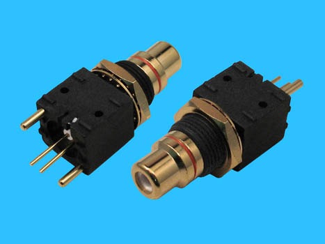
http://www.morethanall.com/upload/products_pdf/15646360353ace67def498.pdf
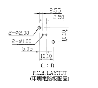
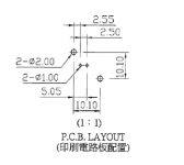
Here is the PCB pattern for the above jack.
Part No: 12HP059-BLACK
Part No: 12HP059-RED
Article No LCHQRCA
Priced $9.89/pair from Hificollective. Could not find on their website.
I wondering if this can work?
RCJ-022 CUI Inc. | Connectors, Interconnects | DigiKey
An externally hosted image should be here but it was not working when we last tested it.
JPS64,
Can you please share with us what the 3D render of the RCA jack looks like so we can find a cheap substitute?
Or is this closer?
http://www.morethanall.com/upload/products_pdf/15646360353ace67def498.pdf
Here is the PCB pattern for the above jack.
Attachments
Last edited:
Hello X,
do you´ve a price for a pair from Morethanall?
We´ve three solutions:
- GB for right RCA PCB high quality but depends on demand
- cheap RCA but will check first PCB replacement and it´s IMHO a bad choice then good preamplifier but bad connectors
- standard rear plate mounted RCA connector connected to PCB using wire
JP
@jwjarch
It´s OK. If short distance between RCA and PCB I would go with simple wire (like Mr. Pass designs).
OK, here a solution:
- use 2p. header, the same as used for X141 to replace all RCA on PCB (2.54mm pitch)
- use assembled 2 wire socket (short length if necessary)
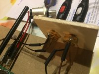
- twist the cable and solder directly on RCA socket (use shrinking tube for isolation and secure fixation)
Photo attached (showing technique for Pass HPA I´ve built).
JP
It´s OK. If short distance between RCA and PCB I would go with simple wire (like Mr. Pass designs).
OK, here a solution:
- use 2p. header, the same as used for X141 to replace all RCA on PCB (2.54mm pitch)
- use assembled 2 wire socket (short length if necessary)
- twist the cable and solder directly on RCA socket (use shrinking tube for isolation and secure fixation)
Photo attached (showing technique for Pass HPA I´ve built).
JP
Attachments
- use assembled 2 wire socket (short length if necessary)
- twist the cable and solder directly on RCA socket (use shrinking tube for isolation and secure fixation)
This works well for me and lets me use the standard RCA panel jacks I have already have. So to confirm, the pitch for the pins is 2.5mm and standard 2pin JST PCB connector can be used here?
Are those Morthenal connectors the correct size? I will have to see if they are even in stock.
Edit: I don't have boards in front of me - I will look at it closely as soon as I can.
Last edited:
- Home
- Source & Line
- Analog Line Level
- AKSA's Lender Preamp with 40Vpp Output