Hi vlv81. From one simpleton to another. It looks like you might be confusing the motherboard (MB) and daughter board (DB) resistors here. Just to make 100% sure – this is what you need:To me they are on the schematic as R14 10k, one for each channel, hence the 1 and 2 after R14.
R141 (MB) – 1 x 10k (Mouser: 71-CMF5510K000BEEB)
R142 (MB) – 1 x 220R (Mouser: 71-CMF55220R00FHEK)
R14 (DB) – 2 x 10R (Mouser: 71-CMF5510R000FHEK)

48V Power supply for AKSA Lender Preamplifier
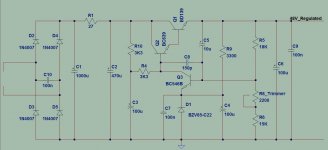
Hello. I was looking for a suitable regulated power supply for AKSA Lender preamp and i came up with this design usually found in old receivers like Sansui,Marantz etc..
Is it a good idea to use something like that?Any other suggestions or improvements on this schematic?
Hello. I was looking for a suitable regulated power supply for AKSA Lender preamp and i came up with this design usually found in old receivers like Sansui,Marantz etc..
Is it a good idea to use something like that?Any other suggestions or improvements on this schematic?
Attachments
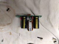
I built the included CLC so I could try some different power supply arrangements. I was under the impression that there would be some voltage drop through the circuit to account for. Hooking it up to a supply that measures 16.4v I still get 16.4v out the other side. What am I doing wrong? Ultimately I want to try a 24v supply for the HPA version I built.
Attachments
Is that a no load test? At no load you aren't going to drop much voltage across the L||R
Yes no load. What would an appropriate load for testing be?
The DCR of that choke (designed for 3-5A) is almost negligible compared to the load for the Aksa Lender (about 100mA max). You won’t see any voltage drop really across the CLC filter. I would not expect to. The drop is going to be across the cap Mx on the board. That’s about 3.5v to 4v, then another 0.5v or so across the CRCRC after it. So the DC supply upstream needs to be 4-5v higher than what you want for rail voltage.
FWIW, member Vunce found that a linear supply at 48v gave much lower noise than a SMPS step up. It’s noise in the 100kHz range so you can’t hear it and neither can the speakers reproduce it.
FWIW, member Vunce found that a linear supply at 48v gave much lower noise than a SMPS step up. It’s noise in the 100kHz range so you can’t hear it and neither can the speakers reproduce it.
Interesting. I never implemented the supplied CRC in my Lender build, but always wondered about where in the chain the CRC would work best – before or after the Cap Mx – or does that not really matter? I might just use the supplied CRC pcb in another project.The drop is going to be across the cap Mx on the board. That’s about 3.5v to 4v, then another 0.5v or so across the CRCRC after it.
X, any news on the PCA daughter boards yet?
Thanks X – I clearly got the filters confused and don’t understand their differences or working yet.The CRCRC is built into the main board and comes after the cap Mx. The small CLC that comes with the amp should be used before the cap Mx.
Great! Cannot wait to hear the PCA boards in the Lender. Your customs are much more efficient than ours - we wait for weeks and with my last import (Parts Express) they hit me with almost 19% import tax.I just got word that the PCBs cleared customs in NY today. I should have them in another day or so.
I am bracing myself for a 25% import tax for “certain goods such as PCBs”. These are the the new trade war tariffs.
The CLC is a high frequency filter designed to stop 100kHz and higher noise form SMPS. Although if you put 1mH ferrite and 1000uF caps it is good down to 100Hz. The CRCRC is supposed to take care of any residual mains 50Hz/60Hz noise and other low frequency stuff.
The CLC is a high frequency filter designed to stop 100kHz and higher noise form SMPS. Although if you put 1mH ferrite and 1000uF caps it is good down to 100Hz. The CRCRC is supposed to take care of any residual mains 50Hz/60Hz noise and other low frequency stuff.
Hi Spiggs,
Thanks. If you have 24v going to the main board you should be fine as there is a 3-4v drop across the cap Mx. You don’t want the voltage to be above 20v and ideally about 18.2v (at the mosfet drain pin). I have a ton of orders to send out this weekend and probably next week too. But should be able to get the smaller orders like yours and Twocents our quickly.
Cheers,
X
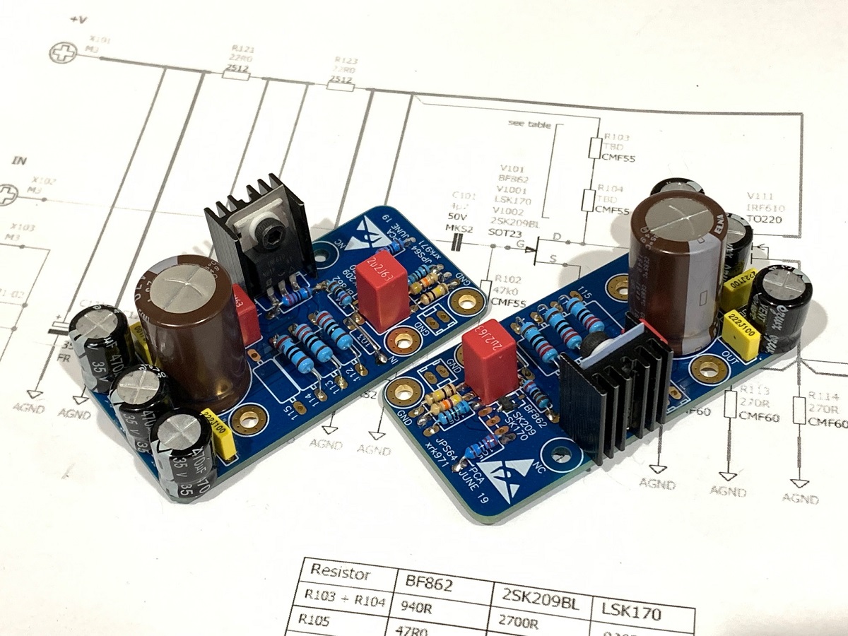
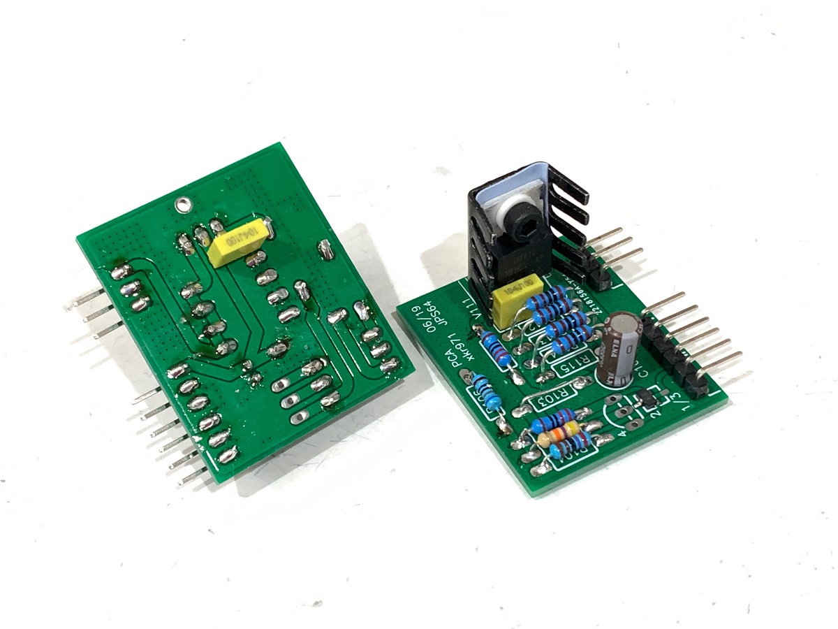
I tested the PCA for the Yarra and it works great. Head to modify the source resistors for setting the proper bias with the Sk209. Looks like the model for the sim was a bit off but using a pair of 2W rated 270R resistors gave me 122mA at a Vcc of 27.5v (yes I know that is high but what I had on Yarra). That voltage won’t kill the board with 2SK209, but would not work for the BF862. I am almost finished building the BF862 and think I will use a setting for a much lower bias of around 60mA for use as a preamp or higher impedance headphone amp.
The YARRA Preamplifier/HPA for Melbourne DB Group Buy
The YARRA Preamplifier/HPA for Melbourne DB Group Buy
The PCA for Aksa Lender has been tested and it sounds great! Easy to build too.
More in the GB thread:
AKSA's Lender Preamp with 40Vpp Ouput GB
More in the GB thread:
AKSA's Lender Preamp with 40Vpp Ouput GB
- Home
- Source & Line
- Analog Line Level
- AKSA's Lender Preamp with 40Vpp Output