Member
Joined 2009
Paid Member
Some fb on the "mysterious" P devices finally and all good points, thanks HD, SJ and J for your inputs!
I assume the advantage of using N devices in VAS is particularly favorable in a blameless type of amp using a bootstrapped VAS, whereas where the complementary type of VAS, even if SE driven, still have to charge/discharge the miller C on the passive side.
FET's vs. BJT's, there the P FET often have a much higher input capacitance compared to an N FET, unfortunately many good JFET's have become unobtaniums.
Member
Joined 2009
Paid Member
Cool movie. Never heard of it before but like the effects.
Never heard of it - Forbidden Planet is one of the greatest sci fi movies of the 50's !
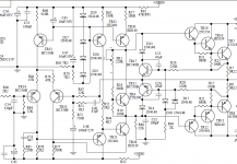
The original Lender circuit was a combined creation of Borbely and Lender in Switzerland almost sixty years ago. They used two opposite gender as the VAS; one driven at base from the left leg of the LTP and the other driven at emitter from the right leg of the LTP. My approximation is almost trivial; it's more an asymmetrical current mirror with free collector taken to the next stage; in this role tethered to an emitter follower at the convenient base emitter resistor comprising a CCS.
In that sense its a modded Borbeley-Lender, but I am attracted to driving both sides of a common emitter because the additional diode relieves the drive at the base, transferring much of the drive to the emitter and this, as a hybrid common emitter/common base transistor it is very, very fast. The additional speed flattens the phase shift and pushes up the high pole.
If we drop Q4, as Juma suggests, we must drive the VAS at 12mA to equal the drive capacity and in truth it's always advantage to drive an output stage at an emitter, since Zout is 26/mA, only 2R intrinsic here sinking current. A VAS collector has very high intrinsic impedance, and the base current is high; say 70uA, using a TO126 VAS, say a KSC2682 or a 2SC3423. The TO92 low parasitic KSA1845 has higher beta and running at 1.5mA the Ib is typically 7uA, unloading the LTP hugely.
Again, a real compromise, somewhat an art, and this seems to perform very well with very low distortion and intrinsic THD 0.143%, H2 at -57dB - gain of 73.8dB without fb at all. This is a very good base from which to add global feedback, and the speed assures easy compensation and wide, deep sound field.
Thanks for the interest. This is a thought experiment for me but if someone builds I'd be very interested in their SQ findings.
HD
Lender's is a challenging circuit for me at least and has become something of a textbook writer's icon. 'Always makes me double take on it for the novelty but it actually turns up several times in commercial products and even in more recent times, among the up-market UK power amplifier designs. This one from Rega, ca. 2000
Attachments
Member
Joined 2009
Paid Member
After some more LTSpice massaging of the sims, it seems a few minor tweaks to the LTP degeneration resistors and adding the additional RC decoupling on the LTP supply as suggested by Juma is a good tip. Will implement on veroboard later tonight after getting back to lab form several days off on travel. Will report back and hopefully using different testing setup will remove the anomalous (not in sims) 5th and 9th harmonic blips.
When a manufacturer adds more features and slaps an inflated price tag on their better performing models, they're often described by the press and enthusiasts as "up-market" as opposed to "entry level" or "flagship", I often read.upmarket ? - what's with the power stage on that, driver emitters loaded on the output ?
Regarding the driver emitters, that arrangement where the driver emitter resistors are returned to the output transistor emitter rather than the output rail, is typical of integrated Darlington devices. I imagine there was no reason it couldn't work in discrete format, when extended to a triple EF form and I'm sure its all been done in audio power amplifiers before. The Rega folk probably found that there was merit in it with this Mira model, at least.
Attachments
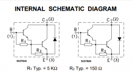
Regarding the driver emitters, that arrangement where the driver emitter resistors are returned to the output transistor emitter rather than the output rail, is typical of integrated Darlington devices.
Many years ago I asked about it in this thread.
")
3 Different Outputstage Driver Arrangements, Your Opinions!
Edit: I must reply to myself and correct me on one thing, hope I get this one right.
I assume the advantage of using N devices in VAS is particularly favorable in a blameless type of amp using a bootstrapped VAS, whereas where the complementary type of VAS, even if SE driven, still have to charge/discharge the miller C on the passive side.
It is not entirely correct assumption, the impact of the miller C on the passive side is dependent on how large the base impedance is, ie. if the miller C is allowed some leeway
through the feedback path can cause the passive VAS transistor to counteract the voltage development on the VAS output and therefore indirectly loading the active side.
Last edited:
The Cob of the passive side is divided by the VAS current gain whereas the VAS miller capacitance is not. Usually though, the passive side Cob is dwarfed by the Cob of the drivers so it's inconsequential (except for those odd designs where the VAS and drivers use the same transistors).
I was borrowing Ultima's words. By "passive side" he means the CCS transistor in a VAS where a CCS is used instead of a bootstrap. By "cause the passive VAS transistor to counteract the voltage development on the VAS output" he means the collector capacitance of the CCS shunts the VAS output, loading it. I had to read that about 5 times myself.
He suggests that Miller effect can increase this capacitance, but I haven't seen that in practice. Usually the current gain of the CCS arrangement is very low (which is what makes it a CCS), and so there is no multiplying of the collector capacitance due to miller effect.
So what I'm saying is that the CCS capacitance loads the VAS output, whereas the VAS miller capacitance loads the VAS input. Hence, the CCS capacitance is divided by the VAS current gain whereas (from the perspective of the VAS input) the VAS miller capacitance is not.
I'm taking the perspective of the error/drive signal as each component contributes to it at the VAS input.
Member
Joined 2009
Paid Member
This is a very clever schematic, I'm going to hazard a guess that the harmonic profile will be very nice.Juma, thank you for the suggested schematic.
New measurements
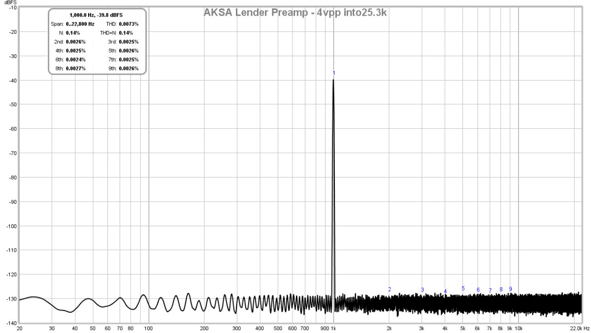
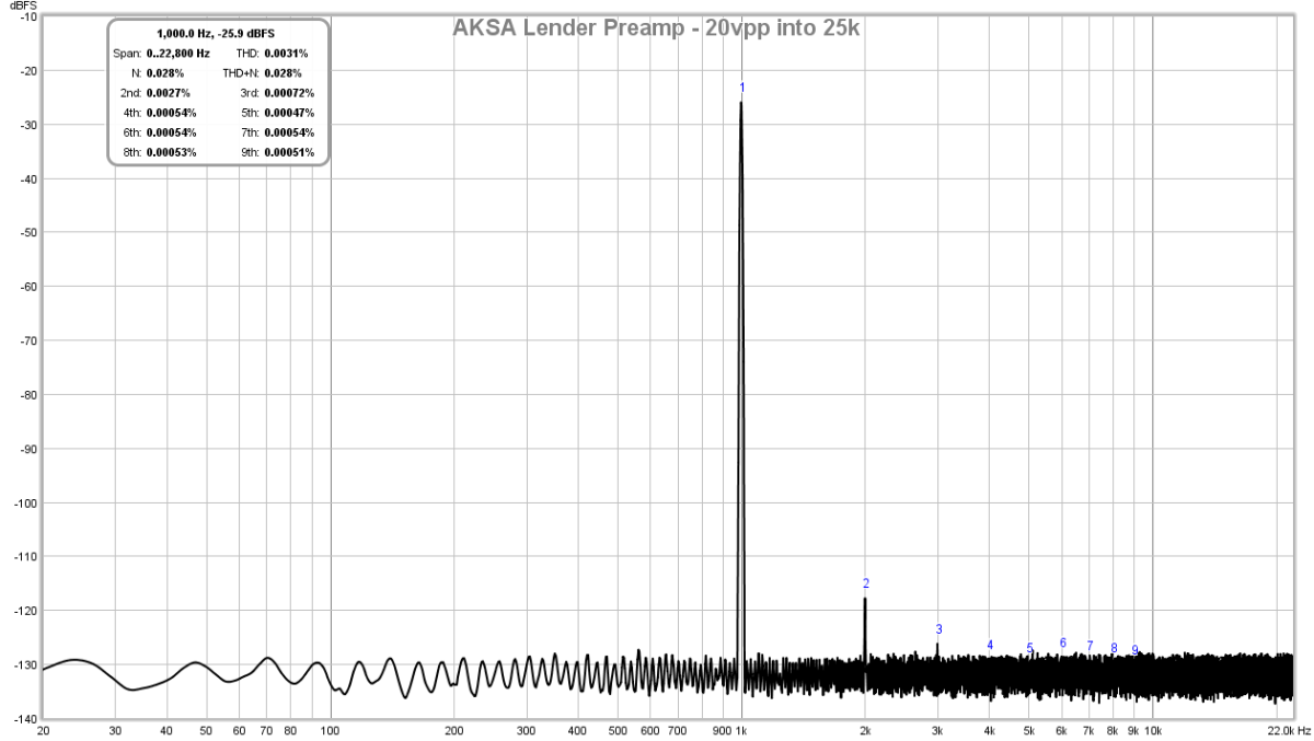
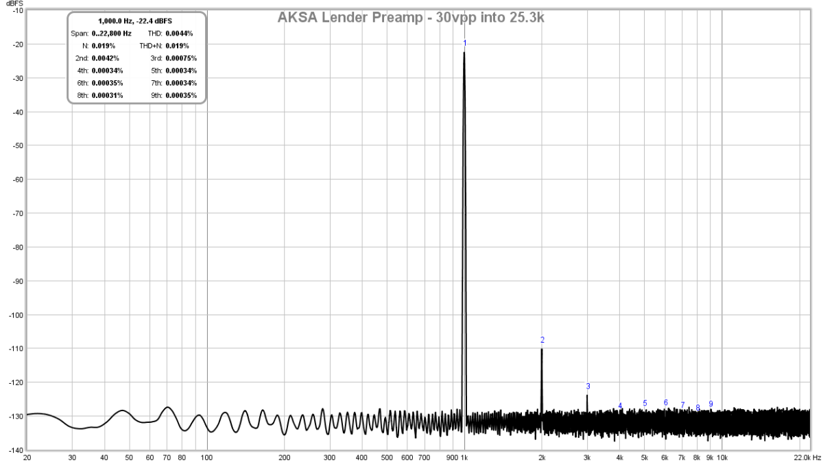
I switched to a new location with less noise and redid the measurement with a quieter laptop and secondary Focusrite. I still got the same 5th and 9th harmonic peaks. Then in REW, under the "Generator" dialog, I clicked "Apply Dither", and the 5th and 9th peaks went away. I unclicked it, and they 5th and 9th peaks did not come back. So apparently, there is some glitch in the sinewave generator. Anyhow, the new measurements now are presented below and look, well, superb. Here is 4v p-p, 20v p-p, and 30v p-p (all my preamp could muster at this gain setting). But the distortion profile remains excellent and the noise floor is still flat and clean. I think that this is a superb result.
4v p-p into 25.3k ohm load:
20v p-p into 25.3k ohm load:
30v p-p into 25.3k ohm load:
Edit: on the 4vpp case I probably need to increase the gain on the audio input as the 10:1 attenuator is putting signal closer to noise floor hence THD actually went up.
Attachments


Last edited:
Yes, most certainly....who needs op amps ?......I think that this is a superb result.
What is the distortion like into low and very low impedance loads ?.
Dan.
I think that this is a superb result.
It is very good.
I use this topology in my amplifier Emprit Amplifier.
Several friends follow the modification that suggested by Mr. Hugh Dean. Some very happy with the modification, some not and stick to the original. By the way, thank you Mr. Hugh Dean.
- Home
- Source & Line
- Analog Line Level
- AKSA's Lender Preamp with 40Vpp Output