Hi belyakove,
When might this happen? On an amplifier input that has a BJT diff pair. Typically there will be from 50 mV to 300 mV DC voltage. Therefore the capacitor has to charge. If one end floats, it cannot charge until you connect the buffer. The charge current has to go somewhere, and a 10 K resistor will offer some path to charge that capacitor. If the capacitor is charged when you release mute, little to no noise will result.
Now you should understand why the mute takes so long to release.
-Chris
You want the capacitor to be in whatever state it is normally in when you release the mute or you will get some noise for certain. When the output is connected, if there is a voltage on the other side of a coupling capacitor, it has to charge. If it charges when the mute is released, the impulse from charging is the same as an input signal.Maybe my question is stupid but if output would be left just unconnected why would that affect output capacitor charge?
When might this happen? On an amplifier input that has a BJT diff pair. Typically there will be from 50 mV to 300 mV DC voltage. Therefore the capacitor has to charge. If one end floats, it cannot charge until you connect the buffer. The charge current has to go somewhere, and a 10 K resistor will offer some path to charge that capacitor. If the capacitor is charged when you release mute, little to no noise will result.
Now you should understand why the mute takes so long to release.
-Chris
Check easy stuff like: do you still get thump with pre-amp inputs shorted to ground?
Do you have any DC offset at output? Have you a buffer on the output and this is causing thump?
According to data sheet, gain is at zero on power up until volume setting is sent by processor.
So activating mute on power up does nothing.
My PGA2320 pre-amp signals power amps on from standby (5v trigger from Arduino pin) and no thumps.
I don't have buffer on output so the PGA is the last stage on the chain. I just tried to set gain of PGA to always 0 and hardly wire MUTE pin to active on my breadboard but power on thump is still present. So it seems that problem cannot be solved without external mute circuit.
Maybe 2320 behaves differently than 2310. However datasheet for these two says the same (unlike 2311)
....Mute transistors are connected with emitter to signal and with collector to ground......
Correct.
Early transistors, C and E were interchangeable. They are both just junctions to B.
Modern transistors are optimized for high amplification at E and high breakdown voltage at C.
They sure can be used in reverse. Typically reverse hFE is not 100+ but about 1. Poor amplifier. But the mute is not an amplifier. The control signal current can easily be much larger than the signal current. It has been a while since I knew this, but reverse connection does have advantages in this odd application.
The problem here is that the "off" E-B junction will break-down at 7 Volts!! This is not a problem for 0.5V-2V cassette decks and similar home hi-fi interconnects. It CAN be a problem if you are running studio levels as implied by this chip and its +/-15V nominal supplies. You are giving-up half your headroom.
I can't believe the PGA part thumps. They were used in large quantities in consoles for fussy users. I'd be looking for stray DC being muted.
I can't believe the PGA part thumps. They were used in large quantities in consoles for fussy users. I'd be looking for stray DC being muted.
I think I tried everything now. I just tried to disconnect PGA's inputs from buffer and connect them to the ground. Zero crossing enabled, MUTE active, gain set by controller to 0. And still have a pop on turn on. Also I tried to connect output via 100 uF electrolytic so all dc should be eliminated. Don't know what else I can try to make it even more silent.
I also found this discussion on TI's forum where TI's employee checked this behaviour on PGA2310 evaluation board. There are measurements from oscilloscope it that thread that show this click during ramp up.
Last edited:
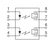
Tried today with a Panasonic photomos relay AQW212EH. I used it to ground the output of preamp and the thump is gone, that's a good thing. Seems that it is a solution that will work. The only question that I have is whether such thing as photomos relay can add some distortion?
Also wanted to try with reed relay but accidentally ordered 12v piece instead of 5v.
Also wanted to try with reed relay but accidentally ordered 12v piece instead of 5v.
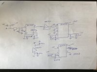
I used a telecom relay to short the output on my latest preamp. Silent startup, very small "thump" on shutdown. Relay stays shorted for 2.5 seconds on startup. Everything is controlled by a 555 timer chip.
Very simple with no fancy parts. I'm quite satisfied and will use this control circuit again.
Very simple with no fancy parts. I'm quite satisfied and will use this control circuit again.
Hi belyakove,
By definition, the relays cannot create distortion in the signal as the outputs are shorted to ground anytime signal current does flow through the relay.
-Chris
I understand that
") But I mean in case when relay is turned off and mosfets are closed. In this case there's still closed mosfet sitting on the signal line. Datasheet for this relay states 1 uA of leakage current.
But I mean in case when relay is turned off and mosfets are closed. In this case there's still closed mosfet sitting on the signal line. Datasheet for this relay states 1 uA of leakage current.Set it up so that the relay contacts you use are normally closed. Apply power to open them. That way they are always closed with power off. Mosfets?
-Chris
This is not electromechanical relay but semiconductor. It's schematic is in the attachment.
Unfortunately it's a single throw relay which is normally open so it's impossible to set it up so mute is on while power is off
Attachments
Hi belyakove,
Not something I would be comfortable with personally. Any reason why you aren't considering a real electromechanical relay? You can get them sealed, filled with inert gas (nitrogen). Those almost never fail and are certainly not going to cause any signal distortion, plus they are naturally in a mute state with no power.
-Chris
Hi belyakove,
Not something I would be comfortable with personally. Any reason why you aren't considering a real electromechanical relay? You can get them sealed, filled with inert gas (nitrogen). Those almost never fail and are certainly not going to cause any signal distortion, plus they are naturally in a mute state with no power.
-Chris
The only reason why I consider electromechanical relay as a last resort is because I wanted to build completely silent preamp.
D3002 TE Connectivity Potter & Brumfield Relays | Relays | DigiKey
Not completely silent, but very quiet.
This is an easy solution for shorting the output that has no effect on the signal.
Not completely silent, but very quiet.
This is an easy solution for shorting the output that has no effect on the signal.
The photocoupler + MOSFET relay can work really well, the contacts never wear out, stick, or pit, and the distortion can be extremely low, better actually than an unsealed relay with certain contacts in the wrong environment.
They also have extremely modest power requirements, especially compared to a coil designed to move a hefty armature with a spring big enough to peel apart mildly "spot welded" contacts.
I understand your apprehension if you've never used them, but they are very easy to design with once you figure them out.
To belyakove: if the photocoupler + MOSFET is a SPST NO, then if you use it in series with the output, it will default to 'off' when unpowered. The advantage of the photocoupler + MOSFET is that it can be used as a very low distortion high side series switch. Add a high value tackdown resistor after the series on/off switch and you have the unpowered off state.
- Status
- This old topic is closed. If you want to reopen this topic, contact a moderator using the "Report Post" button.
- Home
- Source & Line
- Analog Line Level
- PGA2310 preamp turn on mute