Hi,
i would appreciate if someone could help me with the following;
As i am building a custum casing for my tube preamp of alu, this instead of the now used thin platesteel which feels kinda cheap.
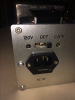
To keep it tidy, i like to remove the AC switch 120/240V as i don’t need it as we have 240V over here.

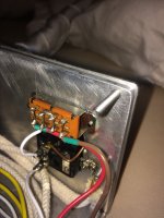
From the transformator there are two wires going to this switch, a brown one, which is on the 120V side and a red one, which is on the 240V side, i presume these are the phase.
There is also a white wire from the transformator to the AC inlet, i presume this is the zero.
In order for me to remove the switch do in need to only use the red one?
And isolate the brown?
Sorry that i have little understanding how this transformator works, hope you can help me out!
Thank you on beforehand!

i would appreciate if someone could help me with the following;
As i am building a custum casing for my tube preamp of alu, this instead of the now used thin platesteel which feels kinda cheap.
To keep it tidy, i like to remove the AC switch 120/240V as i don’t need it as we have 240V over here.

From the transformator there are two wires going to this switch, a brown one, which is on the 120V side and a red one, which is on the 240V side, i presume these are the phase.
There is also a white wire from the transformator to the AC inlet, i presume this is the zero.
In order for me to remove the switch do in need to only use the red one?
And isolate the brown?
Sorry that i have little understanding how this transformator works, hope you can help me out!
Thank you on beforehand!

Hi Gents,
Something strange happened,
i now only have half the volume as i had before.
Could this be related to the switch?
I also replaced some resistors, but with the same R so i don’t understand what happened here?
(replaced some 0.5W PR with 2W AN tantalum’s, same R)
Any advice about the volume? could it be that i needed the brown wire instead of the red?
What would be strange as the brown was on the 120V side of the switch.
What’s going on?
Last edited:
Hi Gents,
Something strange happened,
i now only have half the volume as i had before.
Could this be related to the switch?
I also replaced some resistors, but with the same R so i don’t understand what happened here?
(replaced some 0.5W PR with 2W AN tantalum’s, same R)
Any advice about the volume? could it be that i needed the brown wire instead of the red?
What would be strange as the brown was on the 120V side of the switch.
What’s going on?
I’m afraid you really need to measure some voltages. Seems like your system runs on 120V now? Did you double/triple checked the values on those resistors (sorry to ask)?
I’m afraid you really need to measure some voltages. Seems like your system runs on 120V now? Did you double/triple checked the values on those resistors (sorry to ask)?
Hi,
yes, i did triple checked them, Wattage shouldn’t be a problem, no?
Will try to measure V tommorow, however the transformator is now on the 240V inlet, with red wire, should be correct, i don’t know the V the transformator makes, i don’t have a schematic, jt is from a small company this preamp, and the schematic is not public.
Aah good. Wattage shouldn’t be a problemHi,
yes, i did triple checked them, Wattage shouldn’t be a problem, no?
If you’re in doubt please measure that too, but don’t make yourself too difficult. Measure the wires to that switch first after un-soldering.Will try to measure V tommorow, however the transformator is now on the 240V inlet, with red wire, should be correct, i don’t know the V the transformator makes, i don’t have a schematic, jt is from a small company this preamp, and the schematic is not public.
Also good to make a small schematic on paper.
- Status
- This old topic is closed. If you want to reopen this topic, contact a moderator using the "Report Post" button.
- Home
- Source & Line
- Analog Line Level
- Help appreciated with removal of AC switch in my tube preamplifier PSU.