With VZaichenko's help I've been working on a modular design full featured preamp with the design goal being a very good quality preamp DIY option for experienced builders. The initial design vision is to include single ended and balanced analog inputs, optical and coaxial SPDIF inputs, optional USB input, single ended and balanced output an optional headphone amp. I'm looking at optional FM tuners, Sirius/XM, Bluetooth ect. Control will be open source Arduino based with options for control over Bluetooth, RF, Wifi, IR (any format really). A 2U chassis is the target size for the whole project.
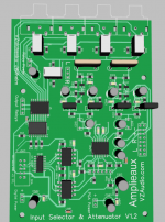
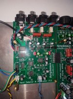
I have a couple prototype boards running so far. The analog design is almost complete. The input board has a couple errors and I need to add some more internal inputs, so it will see at least one more spin. Volume control is done with a PGA2310.
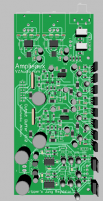
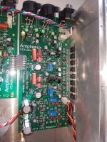
The output buffer board is working very well. It has an onboard Jung regulator designed by Ostripper to clean up the analog input supplies. The output buffers are one of Valery's current drive designs. It has RCA outputs as well as a THAT1646 differential converters for XLR out
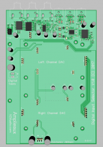
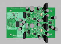
The SPDIF selector board is designed to stack on top of the analog section. I have a first round SPDIF board operating, but I want to add extra inputs for I2S selections. This board also acts as a back-plane for the DACS. Mono PCM1794 DACs with output I-V converters and buffers designed by Valery will stack on this back-plane. These boards contain power supply pre-regulators and regulators locally for all their circuits as needed.
I've designed all digital controls to accept multiple voltages to allow for control from more modern 3.3V microcontrollers.
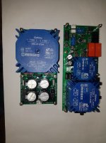
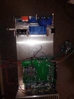
I have power supplies designed to fit in a separate chamber/Faraday cage to the side of the preamp. The analog supply is a simple unregulated supply with CRC design, the Jung regulator on the output board feeds all analog power to the rest of the preamp. The digital supplies is a lot more involved. It has a control transformer that powers all switching and controls with an onboard microcontroller controlling the analog supply and monitoring it's voltage. It has 12V, 5V and 3V3 outputs that are switched by onboard relays for any digital control needs. It also has a second unregulated supply for the DAC and SPDIF boards.
A lot of hours (and dollars) have already gone into this design and there are a lot more to go. I haven't done any formal measurements on anything yet, but the input and output buffers do a wonderful job, not adding anything or taking anything away from the sound. Output noise is under 25uV, so it's dead silent. Ostripper's Jung Regulator design is delivering wonderful clean DC with ripple well under 500uV from no load up to 1A+. The SPDIF switch is performing perfectly. The board outputs I2S signal to the DAC boards with no issues. DAC designs have had a few bumps but are coming along well now.
I have a couple prototype boards running so far. The analog design is almost complete. The input board has a couple errors and I need to add some more internal inputs, so it will see at least one more spin. Volume control is done with a PGA2310.
The output buffer board is working very well. It has an onboard Jung regulator designed by Ostripper to clean up the analog input supplies. The output buffers are one of Valery's current drive designs. It has RCA outputs as well as a THAT1646 differential converters for XLR out
The SPDIF selector board is designed to stack on top of the analog section. I have a first round SPDIF board operating, but I want to add extra inputs for I2S selections. This board also acts as a back-plane for the DACS. Mono PCM1794 DACs with output I-V converters and buffers designed by Valery will stack on this back-plane. These boards contain power supply pre-regulators and regulators locally for all their circuits as needed.
I've designed all digital controls to accept multiple voltages to allow for control from more modern 3.3V microcontrollers.
I have power supplies designed to fit in a separate chamber/Faraday cage to the side of the preamp. The analog supply is a simple unregulated supply with CRC design, the Jung regulator on the output board feeds all analog power to the rest of the preamp. The digital supplies is a lot more involved. It has a control transformer that powers all switching and controls with an onboard microcontroller controlling the analog supply and monitoring it's voltage. It has 12V, 5V and 3V3 outputs that are switched by onboard relays for any digital control needs. It also has a second unregulated supply for the DAC and SPDIF boards.
A lot of hours (and dollars) have already gone into this design and there are a lot more to go. I haven't done any formal measurements on anything yet, but the input and output buffers do a wonderful job, not adding anything or taking anything away from the sound. Output noise is under 25uV, so it's dead silent. Ostripper's Jung Regulator design is delivering wonderful clean DC with ripple well under 500uV from no load up to 1A+. The SPDIF switch is performing perfectly. The board outputs I2S signal to the DAC boards with no issues. DAC designs have had a few bumps but are coming along well now.
Attachments
-
DipTrace Schematic - Inputs and Volume Control V1.3.dch.pdf135.1 KB · Views: 539
-
 Input Selector.PNG198.3 KB · Views: 1,578
 -
DipTrace Schematic - Output Buffer and Regulator.dch.pdf167.7 KB · Views: 414
-
 Output Buffer.PNG208.9 KB · Views: 1,560
 -
DipTrace Schematic - SPDF Switch.dch.pdf168.8 KB · Views: 336
-
 SPDIF Switch.PNG152.5 KB · Views: 1,532
 -
 Input selector.jpg212 KB · Views: 1,584
 -
 Output Buffer.jpg190.8 KB · Views: 1,563
 -
 DAC.PNG313.9 KB · Views: 827
Wonderful news!!!Your testing assistance is always welcome. I'll send you some samples to build and test once they are in final form.
")
The input buffer is fet input. There is a bit of DC on the output, but it's AC coupled to the PGA2310, so it's not an issue anyway. The output buffer is trimmed by R320/420. This is the same input as our VHex+ amps use. It's very stable, only drifting a couple mV from cold to warm operation.
The supplies are assembled and ready for testing. The layout is working out well. Power entry is short and sweet!
Attachments
Hi Jeff,
I can help or offer up my AM/FM tuner design if you want. You might recall I designed a portable radio/media player a few years back now, built 2 protos that have been running this long, so the design seems to be very reliable. The radio was based on a Elektor mag article, project 100126-DSP Radio. This std FM no IBOC(HD)
A user in Germany re-wrote a good portion of the Si4735 code with enhanced RBDS(RDS) code, it filled the mega168. I ported/integrated the enhanced RBDS sw to my xmega platform.
The portable uses some Bourns encoders and a 4x40 LCD display. I use the bottom row as menus for encoders. There is the Si4735, PCM2902B USB codec, BU9458 USB/SD mem stick mp3 file reader as sources for audio.
Sirius/XM I have no idea about. Bluetooth control I have seen a few implementations of, if you want to stream audio over bluetooth I have no idea about.
One option could be a Alps motorized volume pot instead of the PGA2310/20. There is "C" code available for this feature in Elektor project, 071135(Motorized volume control). I have it compiling in Atmel studio 7 which is the dev platform that I suggest or BASCOM-AVR, as it is simpler to understand for most new coders.
One issue is that the code for Si4735 radio chip is it is written in BASCOM-AVR. It is a lot of code, it runs on either a mega or xmega. I suggest to use the xmega which is the mcu I used in the portable due to fact that it the most featured 8-bit mcu that Atmel makes and has the largest flash mem available. You do not want to use a mcu that limits your coding size if at all possible.
So I have a complete radio/media player which is essentially a complete stereo receiver if you want to run with it. Let me know.
I will take a look at your design and offer suggestions if you would like.
Cheers
Rick
Jeff,
I looked at the design a bit. From my design experience I can suggest that you need to step back and work on/consider the user interface(s) and control sections. I think that you are putting the horse in front of the cart. I had a similar issue with my portable design where I did not think the whole design through before committing to h/w first.
I know it is exciting to get H/W in your hands, but pls consider the big picture first.
Have some doc like a block diagram is a great way to have an design overview so that you can best figure out design partitioning and have other do a review.
I can see an issue like putting the mcu on the PS assy, where is your user interface/display functions being put?
Stay away from 5V control, it is legacy = PITA, most I2C and other control I/F's chips are only 3V3! You are not using Arduino H/W so stay away from it. Arduino is intended for using there H/W and adds a level of abstraction to coding, so inexperienced "C" coders do not have to fully understand register level coding access. Thus there is no reason to use Arduino, stick with either Atmel Studio 7 for "C" coding or BASCOM-AVR, which is what I suggest if you want others to help coding unless they have enough "C" experience.
Where is the turn on/off audio muting being done?
I will offer my portable documentation to use as an example if it is of use to you, if I can ever get it to load, if not I can email it to you. I have your email, so I will just send it to you that way.
Last edited:
Hi Rick.
I'd definitely like to have a look at your tuner design. I've already been working on front end design. I'm trying to leave the hardware ready for anything though. I've done a lot of work with Bryan Levin with his remote control design and want to go with something like that. Check out his videos from Burning Amp Festival last year. Cool stuff!
I'd definitely like to have a look at your tuner design. I've already been working on front end design. I'm trying to leave the hardware ready for anything though. I've done a lot of work with Bryan Levin with his remote control design and want to go with something like that. Check out his videos from Burning Amp Festival last year. Cool stuff!
yes I am aware of Bryan's great work and have reviewed some his code, for me it is hard to follow as Bryan is a seasoned programmer.
With coding many times it is easier to write your own code than try to use someone else's code and expect to modify it to suit your purpose, it not as easy to copy s/w as some h/w is to do.
I guess it comes down to who is writing, maintaining and adding additional code/features to your pre-amp project?
front end to what, a tuner? Silicon Labs Si4735,4770 are self contained radio's, no front end is required.
I was referring to the front end of the preamp, controls, display ect. I'll be writing my own code. I prefer to use an open source format like Arduino where there's lots of support and anyone can read and modify code as required. Bryan's package where he's tying all systems into a network is very cool. Using simple GPS style packets is very slick for less experienced coders to interpret. The whole package works very well.
The bottom line is that Arduino is "C" language based and uses the standard gcc avr compiler, as is contained in Atmel Studio7. If you like the Arduino dev platform, best of luck with that, but realize it is "C" and it is not really required. If it is what you are comfortable with using to get the end result of a working pre-amp.
Last edited:
Jeff,
I looked at the design a bit. From my design experience I can suggest that you need to step back and work on/consider the user interface(s) and control sections. I think that you are putting the horse in front of the cart. I had a similar issue with my portable design where I did not think the whole design through before committing to h/w first.
I know it is exciting to get H/W in your hands, but pls consider the big picture first.
Have some doc like a block diagram is a great way to have an design overview so that you can best figure out design partitioning and have other do a review.
I can see an issue like putting the mcu on the PS assy, where is your user interface/display functions being put?
Stay away from 5V control, it is legacy = PITA, most I2C and other control I/F's chips are only 3V3! You are not using Arduino H/W so stay away from it. Arduino is intended for using there H/W and adds a level of abstraction to coding, so inexperienced "C" coders do not have to fully understand register level coding access. Thus there is no reason to use Arduino, stick with either Atmel Studio 7 for "C" coding or BASCOM-AVR, which is what I suggest if you want others to help coding unless they have enough "C" experience.
Where is the turn on/off audio muting being done?
I will offer my portable documentation to use as an example if it is of use to you, if I can ever get it to load, if not I can email it to you. I have your email, so I will just send it to you that way.
The microcontroller in the supply is just controlling the supply. It will look for an on signal from the front panel or the rear panel, or wifi, whichever is required, it will start the supplies up in the proper sequence, then it will communicate to a front panel controller that the preamp is ready to run. The main controller will send out a reset to all the digital devices and ensure they are set to operate correctly.
The PA2310 has a mute function, the DAC has a mute function and the outputs of the output buffer board have relays which can provide muting as well (this is where I plan to mute it). All digital controls can operate on 3V3 or 5V. Valery and I have been experimenting with Arduino Due and ESP boards that operate at 3V3 already.
I'm undecided on front panel volume control. I don't want to use a pot to directly control the volume. I may use one as an input to an AD converter for an input to a microcontroller. I don't want to use a cheap encoder. Those thing feel way too rough when rotating. Bryan found some very smooth industrial optical encoders that we've been experimenting with. They are much higher resolution, and will actually freewheel if you give them a spin. I might actually just use simple buttons though. it's much easier to write software for, and the front panel controls will never be used anyways.
The bottom line is that Arduino is "C" language based and uses the standard gcc avr compiler, as is contained in Atmel Studio7. If you like the Arduino dev platform, best of luck with that, but realize it is "C" and it is not really required. If it is what you are comfortable with using to get the end result of a working pre-amp.
I'm getting fairly comfortable with C now. There's a lot more info available on the internet for C based coding than any other format. Another bonus using C is my daughter just started studying computer engineering in college. The first programming language they learn is C, so we've been teaching each other a few things. She got her first amp running last week. Now she's hooked and is building a VHex+
I am really happy with the cheap encoders in my design, not sure why you think the encoder has to have high resolution, the s/w handles the resolution of each step as in say the volume stepping of each click or step.
Sometimes depending on the complexity of the pre-amp firmware, menus can be a PITA, esp with a small screen.
If your UI is a cell phone that sends control, it is that GUI that has the menus and functions as required to make the pre-amp work as intended. If no cell phone or battery is dead, then you are SOL for control, it is a design decision for functionality and control.
I myself would never use a pre-amp/stereo/tuner, that needs a cell phone to operate, but then again I am old school as I do not even own one.
Writing "C" code for a mcu and a high level computer(PC) are not necessarily the same, as you are not concerned with low level register level coding, you have drivers and a API for that. I can almost predict that when you get experienced with gcc avr, you will find that arduino is a waste of time.
Sometimes depending on the complexity of the pre-amp firmware, menus can be a PITA, esp with a small screen.
If your UI is a cell phone that sends control, it is that GUI that has the menus and functions as required to make the pre-amp work as intended. If no cell phone or battery is dead, then you are SOL for control, it is a design decision for functionality and control.
I myself would never use a pre-amp/stereo/tuner, that needs a cell phone to operate, but then again I am old school
as I do not even own one.Writing "C" code for a mcu and a high level computer(PC) are not necessarily the same, as you are not concerned with low level register level coding, you have drivers and a API for that. I can almost predict that when you get experienced with gcc avr, you will find that arduino is a waste of time.
Last edited:
I wasn't after higher resolution with the encoder. This actually makes them more of a PITA to read. I hate the grinding feel of most encoders. The industrial ones are mounted in ball bearings. Kia or Mercedes, personal preference.
Check out Bryan's presentation and you will see what I'm talking about. YouTube I want multiple options to control the preamp, none of which involve my lazy a$$ getting up out of a chair at the end of the day. IR remote, phone, tablet, PC, whatever. Anything can control the system. Bryan's well on his way to a very slick home automation control.
Check out Bryan's presentation and you will see what I'm talking about. YouTube I want multiple options to control the preamp, none of which involve my lazy a$$ getting up out of a chair at the end of the day. IR remote, phone, tablet, PC, whatever. Anything can control the system. Bryan's well on his way to a very slick home automation control.
1)On the PS/mcu schematic, I see a net called "GND" connected to J1-6(ICSP conn) and the un-named part Q2-9(ULN2xxx?), where else does this net connect too?
2) You are putting regulated voltages through fuses F7-9, why? The SMPS regulators, U1,3,4 have OCP. If you need the fuses, then why not monitor the o/p after the fuses to see if they blew or not. I think you have some spare pins on the m328, adc0-3
3) Does Y1, have internal phase shift caps? More expensive part than a reg xtal. Probably can use the int rc osc fuse option on the m328 and not even need a xtal.
These boards are all just first round proof of concept boards basically. I just put them all together quickly for prototype testing with the intention to test what works and what doesn't then design a final version. The schematics are pretty much just cut and pasted circuits from other designs to get up and running quickly. There will be some anomalies in the schematics.
On the power supply schematic, all grounds are common, whether marked GND or digital GND.
The fuses were an afterthought in case I make a mistake while connecting hot during testing. The final design will monitor these outputs.
The resonator does have internal caps. These are cheap and really easy to install. AWSCR-16.00MTD-T ABRACON | Mouser Canada
I've already found an issue with this board design. I've used this same switching regulator circuit with this same Atmega328 circuit a few times recently. This was all cut and pasted from a previous design. On this board programming was very sporadic and the processor would run fine, then stop working completely for no apparent reason. I finally figured out the Atmega328 didn't like the supply and needed a bead in series with the supply to operate. Silly problems like this are why I do multiple versions and don't sweat the little stuff in the first round.
- Home
- Source & Line
- Analog Line Level
- DIY Full Featured Preamp