At a time when field effect transistors are being deemed as the syncronym of hi-fidelity, it might be eerie for someone to try something like all-BJT. But this idea naturally jumped into my mind when I was tweaking my simple or equivalently cheap vinyl set. I wanted to listen to pure BJT sound. Why? Because back in late 60’s and early 70’s when FETs were still too expensive or too vulnerable to use, probably all vinyl discs were made by ALL-BJT system, from recording, editing to production. I need the original recipe to unlock the original flavor.
I have an all-BJT phono amp and a 1969, which is also all BJT. But my line amplifiers are either tube-based or FET-BJT hybrid. So the whole system is still FET-BJT or tube-BJT hybrid. Forget to find active device pure breed in digital audio system, as they must be FET-BJT hybrid. To build an All-BJT line amplifier, the simplest way might be using all-BJT OP and there’s a range of these types available, such as AD797 that builds its fame on MBL6010. However, personally I prefer discrete transistors over integrated circuits. So OP would not be an option in this case.
I ever made a FET-BJT and silicon-germanium hybrid line amplifier, which in circuit sense, is a variant of Douglas’s design, typically with differential input pair and a single-ended CCS-loaded voltage amplification stage. I want to simplify my design effort by only making minor modification to this successfully-tested circuit. But simply replacing the input different JFET pair with BJT pair will lead to a big problem for a line stage, even not a problem for a power amplifier. We know even after boost-strapping, the BJT differential pair can offer input impedance only around 10K ohms, which would be too low for a preamplifier that is expected to handle subtle and weak signals from source.
So how to solve this problem with minor modification to the circuit? I think I’d try Darlington differential input pair. With Darlington arrangement, the input impedance of the BJT pair can be improved significantly in hundreds of times (about the Beta of the additional BJT)—it seems that LM318 also uses Darlington input differential pair, managing to have input impedance comparable to JFETs with BJTs. Even if the input is coupled to a 10K attenuator, in the full range of attenuation (or the source impedance viewing from the BJT pairs), the higher frequency response can be safely kept up to 1MHz with closed loop, which is validated with 100KHz square wave response.
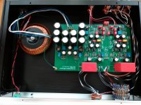
In addition to configure the first stage as Darlington topology, I also configure the second stage (voltage amplification) and the output stage as Darlington topology, to maximize the input impedance of the 2nd and 3rd stages, as increasing the input impedance of each stage might yield a sound effect similar to FET or tube even by actually using BJT, in my opinion. So the final design is an All-Darlington BJT preamp.
Here are some pictures of this hand-made preamp and a video to show the effect of the ALL-BJT system.
页面不存在
I have an all-BJT phono amp and a 1969, which is also all BJT. But my line amplifiers are either tube-based or FET-BJT hybrid. So the whole system is still FET-BJT or tube-BJT hybrid. Forget to find active device pure breed in digital audio system, as they must be FET-BJT hybrid. To build an All-BJT line amplifier, the simplest way might be using all-BJT OP and there’s a range of these types available, such as AD797 that builds its fame on MBL6010. However, personally I prefer discrete transistors over integrated circuits. So OP would not be an option in this case.
I ever made a FET-BJT and silicon-germanium hybrid line amplifier, which in circuit sense, is a variant of Douglas’s design, typically with differential input pair and a single-ended CCS-loaded voltage amplification stage. I want to simplify my design effort by only making minor modification to this successfully-tested circuit. But simply replacing the input different JFET pair with BJT pair will lead to a big problem for a line stage, even not a problem for a power amplifier. We know even after boost-strapping, the BJT differential pair can offer input impedance only around 10K ohms, which would be too low for a preamplifier that is expected to handle subtle and weak signals from source.
So how to solve this problem with minor modification to the circuit? I think I’d try Darlington differential input pair. With Darlington arrangement, the input impedance of the BJT pair can be improved significantly in hundreds of times (about the Beta of the additional BJT)—it seems that LM318 also uses Darlington input differential pair, managing to have input impedance comparable to JFETs with BJTs. Even if the input is coupled to a 10K attenuator, in the full range of attenuation (or the source impedance viewing from the BJT pairs), the higher frequency response can be safely kept up to 1MHz with closed loop, which is validated with 100KHz square wave response.
In addition to configure the first stage as Darlington topology, I also configure the second stage (voltage amplification) and the output stage as Darlington topology, to maximize the input impedance of the 2nd and 3rd stages, as increasing the input impedance of each stage might yield a sound effect similar to FET or tube even by actually using BJT, in my opinion. So the final design is an All-Darlington BJT preamp.
Here are some pictures of this hand-made preamp and a video to show the effect of the ALL-BJT system.
页面不存在
Attachments
Last edited:

Nice work! Are you intending to sell your design as a PCB kit or finished product? If it is purely a DIY venture, we could expect to see your design details, such as the schematic here. After all, without a direct audition and comparison, that's what your design is really about and it then becomes possible to offer constructive comments, exchange ideas etc.Welcome anybody's any comment or recommendation. Whatever.
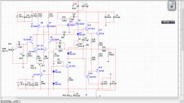
The modification is minor, which can be seen in this schematic figure.
The keys to success include:
1. Properly select amplifcation factor for the transistors of the first darlington pair (such as Q1 and Q4) to ensure under the total static current determined by CCS, the Ic of the first transistor (such as Q1) in the darlington pair will not be too low to work in poor linearity area;
2. As the first stage will have high output impedance for silicon transistor is used as CCS load (silicon transistor features very pentode-like internal impedance, usually in hundreds of Kohms), we need to use transistor with very high amplication factor for Q12 to maximize the input impedance of this stage. Say a transistor with Beta=800 may yield input impedance well beyond 1Mohms.
3. Compensation. Please allow me to leave details about this for privacy. This schematic uses three stages of dalington topoloy and in result, introduces considerable phase shift at the higher frequency. Unfortunately its amplication ability also increases when the phase shift increases, or in other words, it intends to oscillate. To make it work stably under oscillation-critical state, we need to: 1. select transistors with smallest cob; 2. properly use compensation capacitance. After being properly compensated, this circuit can work stably though prone to oscillation. But there is a tale that says a circuit working under oscillation-critical state may have more chances to sound better.
BTW, I DIY for fun. So there would be DIY kit for selling. If you have interest, you can try it yourself.
Attachments
Last edited:
Welcome anybody's any comment or recommendation. Whatever.
c3 too big, increace signal source load less sound quality.
Current through capacitor = cdv/dt.
Take away c3 by using mosfet inputs, increase sound quality.
Last edited:
After being properly compensated, this circuit can work stably though prone to oscillation. But there is a tale that says a circuit working under oscillation-critical state may have more chances to sound better.
IMHO Being prone to oscillation means the amp is not sufficiently compensated. Perhaps you should sim the phase margin of this schematic and see if its at least 45 degrees. That 6pF dominant pole compensation seems quite small...
c3 too big, increace signal source load less sound quality.
Current through capacitor = cdv/dt.
Take away c3 by using mosfet inputs, increase sound quality.
Using BJT will offer much higher Gm than small signal Mosfet, and the sound will be more dynamic. BJT might have Gm like small signal Mosfet, if you use local feedback to reduce BJT's equivalent Gm. In this example, the equivalent Gm of the first pair of BJTs can be reduced to well below 100mS, but still much larger than typical small signal Mosfet working at similarly small static Id , actually 3mA in this circuit. Often under this working point, IRF610 will have Gm at 20-30mS, if you use curve tracer to check it.
The other shortcoming of using Mosfet is that Mosfet will have very large input capacitance (in comparison small signal NPN BJT will have input capacitance smaller than 10pF and Cob below 5pF) and would be inappropriate for a circuit like this, because it has very high open loop gain. And you'd better to have a low output impedance preamp to drive the Mosfet input pair. Not only to drive the high input capacitance, but also to reduce distortion.
In fact the input capacitor can be removed, and the circuit can still work well. Adding it is to protect power amplifier, as it is fully DC-coupled. Any serious DC offset suddenly appearing at the input may cause damage to loudspeakers after it is amplified.
Also one thing you have to know is that the time spent on traversing a capacitor also depends on how large current you can provide, not just dv/dt. And today nearly all signal sources will have a high current buffer as the last stage before the output terminal. Typically if no darlington input is used but a pair of ordinary BJTs, in this topology we need to use 22uF or more to ensure lower frequency response. And this design is widely used in commercial amplifiers.
IMHO Being prone to oscillation means the amp is not sufficiently compensated. Perhaps you should sim the phase margin of this schematic and see if its at least 45 degrees. That 6pF dominant pole compensation seems quite small...
I said "I reserve the proper compensation to my privacy".
You may explore it. It won't be too hard. And this exploration can add fun to your DIY experience.
If everything is crystal-clear, there would be no fun of discovery. Right?
- Status
- This old topic is closed. If you want to reopen this topic, contact a moderator using the "Report Post" button.
- Home
- Source & Line
- Analog Line Level
- All-Darlington BJT Line Pre-amplifier