I added the BoMs:
https://github.com/FutureSharks/preamp-two#bill-of-materials
Many of the parts can be substituted.
https://github.com/FutureSharks/preamp-two#bill-of-materials
Many of the parts can be substituted.
Thanks. For display I don't know yet. I think LCDs look cheap so not so keen on that idea.
You can definitely use cheap encoders! I don't know what problem you had in the other thread but I've used many cheap encoders before without issues. Sometimes they need some hardware of software debouncing but it's definitely possible")
For a display I also didn't like LCDs and in the end settled on a 3.12" 256 x 64 OLED display connected via hardware SPI to a Teensy 3.2 (tiny arduino running at 127 MHz with loads of memory). It's a very sharp display and updates very quickly - perhaps 50 fps or more. Custom fonts and graphics are easy enough to achieve.
I got mine from here: SPI 3.12" ( 3.2" ) 256x64 Graphic OLED White Display ( SSD1322 ) Arduino PIC ARM | eBay
I like your RCA idea.
But how easy was it to solder that chunky metal to the pcb? Did you use a torch? Did you have problems with the plastic insulation?
It was easy with my 100W soldering iron. No issues with the insulation. A small issue is that the PCB warped slightly I think due to the heat but once mounted it sits flat. I think I could avoid this next time by just being more careful and waiting for the PCB to cool between each socket.
Did you try the 805 sockets?
CMC®-Charming Music Conductor.
They should be easier to solder with those spikes at the back. And you would just need two more holes on your pcb part
CMC®-Charming Music Conductor.
They should be easier to solder with those spikes at the back. And you would just need two more holes on your pcb part
The one plus I see with them is that they would go through the pcb, so there should be some more mechanical strength to support the whole thing during operation and while tightening the rings from the outside of the chassis.
With the flat surface soldering, any rotation strength or vibration transfers directly to the copper on the pcb.
With the flat surface soldering, any rotation strength or vibration transfers directly to the copper on the pcb.
I'm in if a group buy for pcb's ever happens.
You can always just take the PCB file and upload it to https://oshpark.com or https://pcbs.io and order. You will get 3 or 4 PCBs.
Hmmm interesting... Too bad it's not for balanced....
You just use 1 MDAC per channel. Or redesign the PCB with a DAC8814 instead of the DAC8812 I used. Easy.
Oldish but interesting project, Max
Do you have documentation on the MDAC board? I’m evaluating possible volume controllers and this one is very attractive compared to bigger and noisier relay based.
Thank you
Oldish but I've been using it almost every day for 5 years now. Still works perfect
Here's my thread that covers the design and prototypes I made: Solid state R2R attenuator using analog switches or multiplying DAC
Some details:
- 65536 linear steps (16bit)
- Any gain possible, set by opamp and resistors
- SPI controlled from an arduino or similar
- Excellent performance (better than PGA2320 in my measurements)
- Can drive headphones
- Can take +/- 10V input
- Compact
- Cost about £35 to build with expensive parts, could be ~£30 with cheaper parts
Try it!
Gotta try it! But many questions arise. For instance:
Any gain possible. Using this small board or the bigger one pictured in the other thread post 42 (“version with gain in the I/V stage, 12dB”)?
Is this SE in/out? Is it possible to be balanced or would that need two boards? And SE in balanced out?
Headphones: I understand tapped after the attenuation, right?
Can take +/- 10V input. Can take or needs?
Thank you again!
Any gain possible. Using this small board or the bigger one pictured in the other thread post 42 (“version with gain in the I/V stage, 12dB”)?
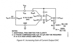
Any of them. The 2 resistors set the gain. See page 18 of this datasheet or the attached pic.
Is this SE in/out? Is it possible to be balanced or would that need two boards? And SE in balanced out?
My design is SE only, yes. Balanced would be 2 boards or redesign PCB with a quad DAC IC instead of a dual, e.g. DAC8814, and a quad opamp.
Headphones: I understand tapped after the attenuation, right?
Not sure what you mean but it's the opamp that is driving the headphones.
I meant signal, not supply. The opamp needs +/- 15 or whatever (depends on the opamp, could be less). Basically the whole attenuator needs digital supply and analog supply, which means +5 and +/- 15 in my design.Can take +/- 10V input. Can take or needs?
Hope that helps! Happy to answer more questions if need be.
Attachments
Thank you for your (quick) replies. These generated more questions though, please bear w/ meHope that helps! Happy to answer more questions if need be.
Ok, some questions related to the gain stage.("Using this small board or the bigger one pictured in the other thread") Any of them. The 2 resistors set the gain. See page 18 of this datasheet or the attached pic.
What's the difference between the two boards?
Can the gain stage be replaced/bypassed by a previous I/V stage or similar from typical DAC boards?
SE is fine, i can generate the differential afterwards.My design is SE only, yes. Balanced would be 2 boards or redesign PCB with a quad DAC IC instead of a dual, e.g. DAC8814, and a quad opamp.
I mean if the headphones output is taken before or after the attenuation.Not sure what you mean but it's the opamp that is driving the headphones.
I think I'm in a big messI meant signal, not supply. The opamp needs +/- 15 or whatever (depends on the opamp, could be less). Basically the whole attenuator needs digital supply and analog supply, which means +5 and +/- 15 in my design.
I thought that the board was getting the value from an encoder throught Arduino SPI interface and somehow (I2C from Arduino?) tells the internal MDAC to use a certain amount of resistance on the audio line. But I was expecting the audio signal to be unprocessed (somewhat similar to the R2R relay attenuators). Not sure I understood a word now
Thank you again for your patience.
SureThese generated more questions though, please bear w/ me
The design is the same but in an older board I used an isolator IC for the digital 5V. It made no measurable difference so I removed it in a later design. I think I've made about 3-5 different PCBs but the design principal is always the same, just with slightly different components or layout.What's the difference between the two boards?
You can make opamp have a gain of 1 by removing the resistors but you can't remove it because it does I/V after the R2R DAC IC. Basically the signal goes from V, converted it I and attenuated by the R2R DAC IC, then converted back to V by the opamp. But to be clear, there is no digital conversion, it's all analog. It just uses a special "DAC" IC that is made of precision R2R resistors.Can the gain stage be replaced/bypassed by a previous I/V stage or similar from typical DAC boards?
I mean if the headphones output is taken before or after the attenuation.
After. The attenuation is done in I. Then signal is converted to V by the opamp, then there is the headphones.
I thought that the board was getting the value from an encoder throught Arduino SPI interface
This is correct. This SPI interface tell the DAC what setting to have. There's 65,000 settings.
But I was expecting the audio signal to be unprocessed (somewhat similar to the R2R relay attenuators)
It is "unprocessed". It's not converting the signal to digital, like with a sample rate etc. The signal is analog the whole time, it's just using a "DAC" IC as an V/I converter with attenuation.
There's more info in the application note from Analog Devices, you can just replace "AC Reference Signal" with "audio": https://www.analog.com/media/en/technical-documentation/application-notes/an-1488.pdf
- Home
- Source & Line
- Analog Line Level
- My new preamp design: Arduino, 6 input selector, MDAC attenuator, IR etc