Looking at your new implementation and code I am tempted to redesign it for MCU running python.
Try it! You'll never want to use old clunky Arduino again
")
I have ordered the pcb of the m-dac attenuator and microprocessor.Great 🎉
I have got an Arduino zero to make a faster test without lost time on develop software.
Unless you use MicroPython or CircuitPython, I think development time will be slower.
Also a little 0.91" I2C display to add in the future.
Cool. Post a photo when it's working 👍
I don't use a remote and did not write any code for it in this version. But there's plenty of examples on the internet to use. I recommend using the Apple remotes as they are high quality.Which remote is compatible with your code ?
I have plans for a preamp with control via WiFi or touchscreen (an E-Paper screen) rather than knobs or bluetooth, and your boards look like a really good starting point. I got some made @ JLCPCB. MCU, attenuator and input switcher, and have a few questions about some of the capacitor values where they're not specified in the schematic (or at least I can't see them)
The Attenuator
The Input Selector
The MCU
C1, C2 don't have values. 100n?
I'm going to use a Feather M0 WiFi that doesn't have the same pinout as the Adafruit board you used, but I'm going to write my own control software anyway and I plan to use breadboard connectors to sort out the differences until I feel confident enough to be able to produce a Feather M0 MCU. Will it be OK to base my design on yours? Happy to keep logos etc, and also to send the Kicad project for you to add to your github repository if you'd want it.
Selector Boards
I want to have output switching options available to me, to be able to switch between single ended and balanced for example, also to include a switchable warp filter on phono. My plan is to use additional input selector boards either fully or partially populated. One for inputs, one for outputs and possibly one for 'jumper' options. So three in all.
I don't see any problems with this in principle because I'm writing the software, but this is all a learning experience for me and I wondered if you have any thoughts on bending your design in this direction
The Attenuator
- Values for C2, C3, C5. I'm not exactly comfortable with Kicad so it may be I'm just not interpreting the schema/PCB layout, apologies in advance...
- All JLCPCB boards have bridges across two pairs of pads of U2: 4GND&5GND, 14GND&15GND. If I've interpreted the schema+PCB layout correctly this is as specified. But like I said above...
- When I open the attenuator schema I get a message about a missing library file: \users\max\git\preamp-two\mdac_att...\DAC8812.lib It's not that much of a problem as the project appears to have cached a 'last used' value, but I thought I'd mention it.
The Input Selector
- C2, C3, C4. I'm assuming 100n as that matches with the attenuator board.
- C1
The MCU
C1, C2 don't have values. 100n?
I'm going to use a Feather M0 WiFi that doesn't have the same pinout as the Adafruit board you used, but I'm going to write my own control software anyway and I plan to use breadboard connectors to sort out the differences until I feel confident enough to be able to produce a Feather M0 MCU. Will it be OK to base my design on yours? Happy to keep logos etc, and also to send the Kicad project for you to add to your github repository if you'd want it.
Selector Boards
I want to have output switching options available to me, to be able to switch between single ended and balanced for example, also to include a switchable warp filter on phono. My plan is to use additional input selector boards either fully or partially populated. One for inputs, one for outputs and possibly one for 'jumper' options. So three in all.
I don't see any problems with this in principle because I'm writing the software, but this is all a learning experience for me and I wondered if you have any thoughts on bending your design in this direction
I have plans for a preamp with control via WiFi or touchscreen (an E-Paper screen) rather than knobs or bluetooth, and your boards look like a really good starting point. I got some made @ JLCPCB. MCU, attenuator and input switcher
Sounds great, post some pics
have a few questions about some of the capacitor values where they're not specified in the schematic (or at least I can't see them)
Sure...
The Attenuator
Values for C2, C3, C5. I'm not exactly comfortable with Kicad so it may be I'm just not interpreting the schema/PCB layout, apologies in advance...
These caps are just larger power supply bypass capacitors. The value is really not critical, probably any value that fits that footprint and is an electrolytic will be fine. I used 100uF, as you can see in the BoM: preamp-two/PCBs/mdac-attenuator at master * FutureSharks/preamp-two * GitHub
All JLCPCB boards have bridges across two pairs of pads of U2: 4GND&5GND, 14GND&15GND. If I've interpreted the schema+PCB layout correctly this is as specified.
That's correct, those are all ground. You can see in the DAC8812 datasheet what the pins are.
When I open the attenuator schema I get a message about a missing library file: \users\max\git\preamp-two\mdac_att...\DAC8812.lib It's not that much of a problem as the project appears to have cached a 'last used' value, but I thought I'd mention it.
Oh I see, the file path is the path from my computer. The file is here, I think you just need to update the part lib path or something inside kicad.
The Input Selector
C2, C3, C4. I'm assuming 100n as that matches with the attenuator board.
Yes, value is in the BoM: preamp-two/PCBs/input-selector at master * FutureSharks/preamp-two * GitHub
Same as C2/C3/C5 from attenuator, this is just a larger bypass capacitor. Value is also in the BoM.
The MCU
C1, C2 don't have values. 100n?
These are just small bypass caps close to the ICs. This is common/good practice, 100nF will be fine.
I'm going to use a Feather M0 WiFi that doesn't have the same pinout as the Adafruit board you used, but I'm going to write my own control software anyway and I plan to use breadboard connectors to sort out the differences until I feel confident enough to be able to produce a Feather M0 MCU.
Sounds like a solid approach!
Will it be OK to base my design on yours? Happy to keep logos etc, and also to send the Kicad project for you to add to your github repository if you'd want it.
Of course that's OK, that's desired, it's open source
You don't have to keep logos or anything like that. Change it as you wish, you just legally have to follow this: Page Not Found - TLDRLegal)Selector Boards
I want to have output switching options available to me, to be able to switch between single ended and balanced for example, also to include a switchable warp filter on phono. My plan is to use additional input selector boards either fully or partially populated. One for inputs, one for outputs and possibly one for 'jumper' options. So three in all.
Sounds good!
I don't see any problems with this in principle because I'm writing the software, but this is all a learning experience for me and I wondered if you have any thoughts on bending your design in this direction
The input selector is just a mechanical switcher so in theory could be used in either direction I guess. As each unit is switching a L/R pair, a single unit could also be used to switch a single balanced connection, so you can just use 2 units for full balanced L/R. But one thing to note is the mute relay, it connects output signals to GND, but you could just leave the mute relay/connectors out/unpopulated. Or just redesign it as you wish.
Sounds like a great project, be sure to post some more details and feel free to ask anything further
Is correct this power supply connection and values ?
see photo
Yes that is correct. I used 5V for digital but 3.3V will also work. I think the opamp can also run on +/- 5-18v.
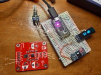
The my Arduino M0 during the test have lost the bootloader so I have used a STM32 module to control the MDAC with SPI.
Good result also in the first measurements without the power supply by-pass caps
Vin 1.5Vrms
Vout 6Vrms at 0dB with 0.0047% thd
-10dB with 0.0073% thd
-20dB with 0.0055% thd
Good result also in the first measurements without the power supply by-pass caps
Vin 1.5Vrms
Vout 6Vrms at 0dB with 0.0047% thd
-10dB with 0.0073% thd
-20dB with 0.0055% thd
Last edited:
Nice. How did you take the measurements?
At this time the my Victor 1Khz reference oscillator does not work so I have used a DAC PCM5100 to generate the sine and Olivine 2 as ADC with Software Arta.
Probably this thd value is the same of input signal.
maxw,
your project is beautiful and very well done.
thanks for sharing.
Thank you mlloyd1
- Home
- Source & Line
- Analog Line Level
- My new preamp design: Arduino, 6 input selector, MDAC attenuator, IR etc