Wow man, I thought I got it the 1st time, but has taken me longer. I get it now. Thank you. Also read several docs from AD linked from your pdf link in the original design post, like these two
The Data Conversion Handbook, 2005
New High-Resolution Multiplying DACs Excel at Handling AC Signals
Figures in the later are excellent.
So, in summary. I think I want to do this. I will need a previous gain stage but that’s another story. Do you have boards to sell? Gerbers? ...? BOM?
Thank you again
Also read several docs from AD linked from your pdf link in the original design post, like these two
The Data Conversion Handbook, 2005
New High-Resolution Multiplying DACs Excel at Handling AC Signals
Figures in the later are excellent.
Cool, now I think you know more than me

So, in summary. I think I want to do this. I will need a previous gain stage but that’s another story. Do you have boards to sell? Gerbers? ...? BOM?
Thank you again
No boards and but I have code and PCBs files. You can upload both KiCAD and Eagle PCB files directly to oshpark and order them yourself.
My later PCB files are here: preamp-two/PCBs at master * FutureSharks/preamp-two * GitHub
I've also posted other versions of the PCB files many times.
Basic BoM is here: GitHub - FutureSharks/preamp-two: An Arduino controlled high fidelity preamplifier
Arduino code: https://github.com/FutureSharks/preamp-two/blob/master/code/preamp-two.ino
CircuitPython code: https://github.com/FutureSharks/preamp-two/blob/master/code/modules/mdac_attenuator.py
No wayCool, now I think you know more than me
No boards and but I have code and PCBs files. You can upload both KiCAD and Eagle PCB files directly to oshpark and order them yourself.
My later PCB files are here: preamp-two/PCBs at master * FutureSharks/preamp-two * GitHub
I've also posted other versions of the PCB files many times.
Basic BoM is here: GitHub - FutureSharks/preamp-two: An Arduino controlled high fidelity preamplifier
Arduino code: preamp-two/preamp-two.ino at master * FutureSharks/preamp-two * GitHub
CircuitPython code: preamp-two/mdac_attenuator.py at master * FutureSharks/preamp-two * GitHub
Awesome! I will study those boards and choose. Arduino shouldn't be the bottleneck here, I'm more worried about my (lack of) electronics knowledge (working on it). Look what I found in a box this morning:

I have to study the datasheets to see if I could use any of the two in your design but looks promising.
A final question (for now
). What's the main difference, if any, between the MDAC approach like yours and using a digital volume controller like WM8816, PGA2310 or MUSES72320Thank you again
I _think_ both are conceptually very similar approaches. See Analog Devices MT-091 Digital Potentiometers.What's the main difference, if any, between the MDAC approach like yours and using a digital volume controller like WM8816, PGA2310 or MUSES72320
BTW are you storing the volume on EEPROM or does the MDAC have Non-Volatile memory?
What's the main difference, if any, between the MDAC approach like yours and using a digital volume controller like WM8816, PGA2310 or MUSES72320
That's a good question. I'm not super knowledgable to be honest. Someone else can probably explain better.
From the PGA2310 datasheet:
The heart of the PGA2310 is a resistor network, an analog switch array, and a high-performance bipolar op amp stage. The switches select taps in the resistor network that determine the gain of the amplifier stage.
I think the WM8816 is the same design but with external opamps. The MUSES72320 looks a little more simple but also with external opamps.
BTW are you storing the volume on EEPROM or does the MDAC have Non-Volatile memory?
Nope. If you want any memory of any settings you have to implement this in the micro controller. Most Arduinos have EEPROM.
Is there an easy place to connect the input signal if the DAC of choice is already current out?
Maybe but then you have a very different design, you would have to test it yourself.
That's a good question. I'm not super knowledgable to be honest. Someone else can probably explain better.
I think the main difference is resolution, in theory is easier to find DACs w/ higher resolution than digital pots. But I may be wrong.
Nope. If you want any memory of any settings you have to implement this in the micro controller. Most Arduinos have EEPROM.
Sure. I'm thinking about using the RPi directly as the micro controller (probably in python).
Maybe but then you have a very different design, you would have to test it yourself.
I might end up using your design, but I think I'll investigate a bit by my own for a bit. Thank you again for all help.
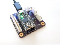
Small update
I switched from Arduino to Adafruit ItsyBitsy M0 Express. Once you used one of these newer micro controllers that runs MicroPython or CircuitPython you honestly don't want to go back to the crappy old Arduino way. It's so much better!
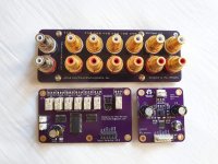
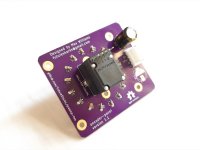
Anyway, problem is that they are all 3.3V so I redesigned my input selector and attenuator to be 3.3V compatible.
I switched from Arduino to Adafruit ItsyBitsy M0 Express. Once you used one of these newer micro controllers that runs MicroPython or CircuitPython you honestly don't want to go back to the crappy old Arduino way. It's so much better!
Anyway, problem is that they are all 3.3V so I redesigned my input selector and attenuator to be 3.3V compatible.
Attachments
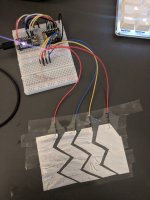
I was thinking more about control and tested out a bunch of different methods for control. An encoder or pot is an obvious option but I wanted to try some alternatives. I made some prototype touch interfaces based on some capacitive touch control ICs and a light based one.
An externally hosted image should be here but it was not working when we last tested it.
Attachments
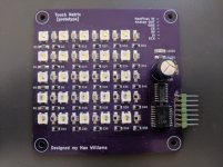
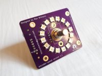
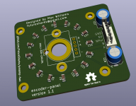
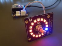
But in the end I couldn't make something that felt perfect so I went back to an encoder based input. I used a ring of 16 NeoPixels to for visual feedback.
An externally hosted image should be here but it was not working when we last tested it.
Attachments
Awesome!
Also, what's that pretty keyboard on the top right corner? Have a link?
It's just a Magicforce 68. Not bad mechanical keyboard
It's just a Magicforce 68. Not bad mechanical keyboard
WOW, < US$50 mechanical keyboard? Is this even possible?
Very interesting project! Thanks for posting, and for making your designs available.
No worries. To be clear, all the PCB files, designs and code is here: GitHub - FutureSharks/preamp-two: An digitally controlled high fidelity preamplifier 🔈🎵
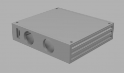
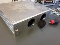
Finished the MCU board now: preamp-two/PCBs/mcu-board at master * FutureSharks/preamp-two * GitHub
Attachments
There's some more prototype photos here: preamp-two/images/prototypes at master * FutureSharks/preamp-two * GitHub
An externally hosted image should be here but it was not working when we last tested it.
- Home
- Source & Line
- Analog Line Level
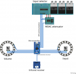
- My new preamp design: Arduino, 6 input selector, MDAC attenuator, IR etc