P.S.
Let us know the voltage gain of your power amp and the sensitivity of your speakers. So we can suggest a logical voltage gain setting for your preamp. Setting a very wrong line level gain can ruin the useful range of volume control and worsen the signal to noise ratio in any audio system.
Let us know the voltage gain of your power amp and the sensitivity of your speakers. So we can suggest a logical voltage gain setting for your preamp. Setting a very wrong line level gain can ruin the useful range of volume control and worsen the signal to noise ratio in any audio system.
25.1V at a psu section output indicates a fault. Seems like the rectified dc level passes straight through. You could be having wrong or broken same position TO-92 small transistors in those two high output sections. Maybe PNP and NPN swapped over. Check the types and their places closely first.
Thanks a lot!
Mixed up two of the Q1/Q3...
 Good advice in Your build-guide not to solder the heat-sinks before making sure everything is OK!
")
For the moment I have a Maya 200 29db and my F4 0V on the input and I can use either one to go into my Thor evo 4 speakers 89db.
My reasons for asking about gain concerns next years project which will be this,The-Loudspeaker-2
These speakers have a system sensitivity of 95db and require bi-amping.
My idea is to use the F4 to drive the MT section which derives its gain from the preamp and have the Maya running the bass.
I won't be using headphones so that is not a consideration, looking at the figures supplied if I use 499R that would give me a gain of 9.54 and then I could put a minus 20db inline attenuator on the Maya which would give me a gain of 9db, a pretty good match.
I am just trying to use the things that I already have but another possibility is to buy a class D power amp for the bass with adjustable gain then I can adjust it to whatever suits.
If you have any other suggestions I'm all ears.
So you mixed the big ones. Luckily those are difficult to break when mixed up. There's a good chance they will still work when restored in their right places. Not always 100% but a good chance.
Paying attention to the little details, and missing the obvious...
@66deg
The DCG3 has much open loop gain to leave space for setting it for whatever closed loop gain i.e. the gain you use. I have seen up to 15dB that someone had used here. Its spec will be progressively compromised as you go higher gain because the gain you use its relocated from being available for feedback.
Best IMO will be to have a normal gain preamp compatible with many other gear and a class D powerful economic amp like a Behringer with input gain pots for relegating bass duties to it.
So you mixed the big ones. Luckily those are difficult to break when mixed up. There's a good chance they will still work when restored in their right places. Not always 100% but a good chance.
It seems I’ve been lucky, but one side is a bit off with 17,41V? Can I leave it like that, or is it a bit too much?
V+>G=17,19V G>V-=17,41V
V+>G=17,19V G>V-=17,22V
DCG3 will not produce offset by such rail assymetry. Its single ended Class A with CCS. Its balance stays.
That 1.2% difference for an auto setting PSU is little. There are parts tolerances.
Sounds Good, and I’m happy with that! Thanks again for helping all of us getting back on track and learning by doing it! It’s highly appreciated!
Thanks, I will put in the 3x and sort the amp situation out after building The Loudspeaker.
Your help and advice are much appreciated.
A miniDSP digital crossover box can also equalize gain between different active branches to amps. On top of customizing curves and delays for a very versatile speaker optimization approach.
In any case 29dB gain is 28 times. To achieve that, R6 should be near 13.5k. Two 27k in parallel are equivalent to that. I don't know if there could be any practical oddities, we never tried it up there, but LT Spice shows it working. THD will be worse than in normal gain builds when pushed for level, especially for full blast near rail to rail output swing.
Sounds Good, and I’m happy with that! Thanks again for helping all of us getting back on track and learning by doing it! It’s highly appreciated!
I have had a quick read about the mini DSP and it looks very interesting , as I have no WAF considerations in the workshop one power amp per driver shouldn't be a problem.
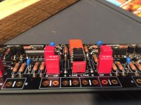
Progress is being made on the board but I would just like to check orientation of J1/J2 with the printed side towards the printing on the board? image below.
Thanks.
Progress is being made on the board but I would just like to check orientation of J1/J2 with the printed side towards the printing on the board? image below.
Thanks.
Attachments
Salas, just read of the BC327-40 mod. How many should I buy to sort through? Datasheet suggests an average hfe of 400, max 630, making a need for around 500 hfe on the upper end of specs.
Also, I’ve searched and can’t find the answer but, if I drop the gain to 2, how do I do it (r6?) and will it compromise the sound of my unit, which I’ve been very happy with.
I’m building the Pass DIY VFet amp and will be running 99db drivers in a TQWT so the gain in the DCG3 may be too much.
Also, I’ve searched and can’t find the answer but, if I drop the gain to 2, how do I do it (r6?) and will it compromise the sound of my unit, which I’ve been very happy with.
I’m building the Pass DIY VFet amp and will be running 99db drivers in a TQWT so the gain in the DCG3 may be too much.
@66deg,
You already put the op-amp in place?
Maybe you can check again the guide:
You already put the op-amp in place?
Maybe you can check again the guide:
7. DC offset
If all is ok and warm, short the signal inputs and measure the DC offset across each line output. It may read many mV at first because VR1's half point starts at a relatively high value for the purpose. Tweak VR1 per channel to the narrower range of hovering mV around zero DC you can. Don't expect it to stop moving about because it will not. Shut down.
Measure that the rails are down to zero volts first. Put the op-amp in the socket with its dot oriented towards the relay. Power up. A minute after the click verify that the DC offset is very low in mV. It may prove less than 1 mV even but not all op-amps are doing the same.
- Home
- Source & Line
- Analog Line Level
- Salas DCG3 preamp (line & headphone)