Very nice savvas
Yours going well in its very initial stages as I also see
Savvas,
Looks like a small heatsink for the DCG3. How hot does it go?
Not much, just warm (30 minutes on) but we still have cold weather and it's not in a closed chassis, so in the end I'm gonna have a bigger heatsink or maybe a quiet fan.
Before tweaking the offset trimmers or after?
Before, haven't touched the trimmers yet.
With heatshrink on transistors there is little bit higher dc offset but with less drift (min, max)
Is there any benefit shooting for less dc offset by changing transistors ?
See about DC offset & drift after having tweaked the 20 Ohm trimmers. Because 95% of the now offset is due to their initial position. Only their low 2-4 Ohm range is usually needed to null the transistors contribution in this circuit. After that step you can judge better the semis lowest adjusted offset or if they tend to drift bit more vs other pairs.
Thank you,
but like the germans said “langsam aber sicher”,
and the Greeks “σπευδε βραδεως”
Slowly but surely.
But I must say most of Salas's project don't have hidden factors and buying the kit makes the things even more easy.
In short, you are almost there. Don't rush with the cables, it's better than you know all connections are done right.
See about DC offset & drift after having tweaked the 20 Ohm trimmers. Because 95% of the now offset is due to their initial position. Only their low 2-4 Ohm range is usually needed to null the transistors contribution in this circuit. After that step you can judge better the semis lowest adjusted offset or if they tend to drift bit more vs other pairs.
Thanks, will do just that.
The stepped attenuator is a Allo Ladder type 10K, and for $29 is a bargain. The down side of a 10K attenuator is the load it presents to the source.
Hello, can you do me a favor? When again on the bench to measure the slew rate at the preamp's output when using this ladder pot? At unity gain and at full gain both on 1kHz 1VRMS square wave from the gen? Because I don't have data on that with other than series pots.
P.S.
When having the trimmers set down to zero Ohm you may also see the semis pure offset when completely unaided.
You are right, the trimmers by default are in the middle (soldered them as the were set) so semis offset must be higher.
Anyway, it's for academic purpose I think. I'll just zero the offset and get on with the tests.
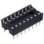
BTW the best socket for Jfets and transistors I find that it's dil sockets, just like this one
Very good grip, unlike the ones with circular contacts which might or might not work
Attachments
Very good grip, unlike the ones with circular contacts which might or might not work
I have had good experience with circular ones but when with rather short pins left on the semis.
I have had good experience with circular ones but when with rather short pins left on the semis.
I thought that all circular pin sockets for chips are about the same more or less or at least big enough for transistors legs (TO 92) to fit tight but it's not the case with some
I had to desolder them because the transistors were much too loose (thank the Almighty I have a desolder machine and GB pcbs are top quality)
It's better to be on the safe side and not to worry if a blowing by the wind throws your transistor off the board.
Now I'm populating the dcb3 board, I see parts kit for R4, R5 a Dale 33R2, and wonder if makes sense replace them to a somewhat higher value 43R but higher quality tantalum resistor that I have without use.
Lukily I have also in spare bin Vishay naked TX2352 for important places as R1, R6 and R15.
Lukily I have also in spare bin Vishay naked TX2352 for important places as R1, R6 and R15.
Last edited:
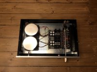
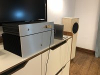
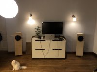
I encased mine today, as I've been listening to it over 3 weeks already and I absolutely loved it. Precise, in control, very reavealing. Japanese knife type when with SMD 20K stepped pot and monitorish headphones. When with my fresh DIY FL speakers and a current feedback AB/A type amp it made me experience almost spooky presence moments during some musical passages. Now it is test running a TKD pot together with the speakers. And it makes me appreciate a tone correctness of some live instruments with a smile. The speakers need some tuning, so I can't tell the final word which pot is here to stay. More discoveries are waiting 
The build was sans glitch. The documentation was clear and top notch. I'm very grateful to Salas, Tea-bag and the community.
Can't be streesed enough, Diyaudio is a truly special place on the net. The internet was built for the Diyaudio, not the other way around. The knowledge that is shared here is overwhelming and priceless. I've been to many online communities, but for me this place is a reference in terms of many things.
And of course, Salas is one of and also THE gem of this kingdom. Thank you, Nick, for everything.
All this to say, if you're on the fence of building this, go for it!
Some DCG3 pics with my audio family.
Attachments
Last edited:

I have eight 2sk170
Hfe:
666, 677, 732, 794, 829, 980, 1049, 1216
Please Salas, which ones are best pair for J1/J2 ?
I see on datasheet 1-d / 2-g / 3-s,
But on circuit board order pinout is different, drain hole is in between. Maybe Ok. Just wanted to confirm if I need to bend the Drain lead.
Hfe:
666, 677, 732, 794, 829, 980, 1049, 1216
Please Salas, which ones are best pair for J1/J2 ?
I see on datasheet 1-d / 2-g / 3-s,
But on circuit board order pinout is different, drain hole is in between. Maybe Ok. Just wanted to confirm if I need to bend the Drain lead.
Last edited:
2SK170 is a JFET thus it can't have Hfe, that parameter is for bipolar transistors. Maybe you mean something else?
There is no need to bend their pins for proper orientation, you just face one 2SK170 the other way from the next. Board for uPA68 is DGS SGD with a no connection SUBstrate pad in between.
There is no need to bend their pins for proper orientation, you just face one 2SK170 the other way from the next. Board for uPA68 is DGS SGD with a no connection SUBstrate pad in between.
- Home
- Source & Line
- Analog Line Level
- Salas DCG3 preamp (line & headphone)