You can damp down the line gain further from times two with a voltage divider at the output. Replacing the 50 Ohm (R15) with a 470 Ohm, then adding another 470 Ohm across the output RCA. That brings a side effect of enlarging the output impedance, which might not be a problem for driving your amp if it has at least 10k input impedance, but it will also bring net gain of times one. Since you are looking for even less gain still. Your amp and speakers combination is probably sensitive. If unity gain proves rather low for you, you can bring it up to one point five by restoring the main gain setting to three.
Those are otherwise good 1kHz plots. To start with measurements compatibility, load it with rather low impedance headphones also and measure at 400mV RMS across various frequencies.
Salas, I'd like to plot mine too using a Focusrite and Arta. I dont have headphones. Should I use a 1k resistor as a load? Do you mean I should dial in the input with the Focusrite and measure 400mv across the load? Pot at max volume?
Thanks. nash
On all plots in post#1 there are loads mentioned. They were done at 400mV RMS across the loads or there about. To avoid the measuring audio card's elevated own THD components adding when approaching zero dBFS. Real loads also have reactance but you can replace them with resistors. The pot was normally used so to be in the game as with everyday use. Set 1V RMS on the generator. The sweeps were done with ARTA Steps. Watch not to clip the card's input.
Checked the pot and it does appear to be 20k - reads 18.4k when closed across the in/out pins (7 o'clock position) and at the 10 o'clock position (my normal listening level) it's reading 17.8k across in/out.
The manual for my amp says input impeadance is 10k unbalanced RCA amd 33k Main Input. I'm just using the amp as a power amp and have enabled the 'separate' function and have connected the DCG3 to the 'Amp In' connection so I'm guessing that's the 33k input? Amp is a Perreaux Eloquence 250i and I've currently got Tannoy Mansfield with 15" HPD's (92dB) connected up but I also use Monitor Audio PL300's (90dB).
Do I put the 470 ohm directly across the L/G and R/G outputs - is it best to solder the resistor on the underside of the board at the output connectors or is there a better place?
The pot is within right range value. Is there any source equipment you use that has a warning against such a line input impedance value, asking for 50k or more? I believe its Log type also, yes? Because linear pots turn up subjective volume way early.
Your integrated amp's manual says main inputs 33kΩ(RCA) so not a problem having 470Ω source impedance from the preamp. It may even damp the system better if it was little prone to treble with the specific amp and interconnects.
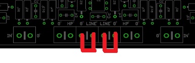
One 470Ω replaces R15 in each channel. The other one goes between tip and barrel of the line output RCA. But you can alternatively place it underneath the PCB between the line out and line GND pads of each channel.
Your integrated amp's manual says main inputs 33kΩ(RCA) so not a problem having 470Ω source impedance from the preamp. It may even damp the system better if it was little prone to treble with the specific amp and interconnects.
One 470Ω replaces R15 in each channel. The other one goes between tip and barrel of the line output RCA. But you can alternatively place it underneath the PCB between the line out and line GND pads of each channel.
On all plots in post#1 there are loads mentioned. They were done at 400mV RMS across the loads or there about. To avoid the measuring audio card's elevated own THD components adding when approaching zero dBFS. Real loads also have reactance but you can replace them with resistors. The pot was normally used so to be in the game as with everyday use. Set 1V RMS on the generator. The sweeps were done with ARTA Steps. Watch not to clip the card's input.
Thanks for the details. nash
Since my integrated amp isn't in my long term plans I think for now I'll just run the DCG3 through the integrated pre-amp and set this volume to a level which allows me to use more of the travel on the DCG3 volume controller - saves me messing too much with the DCG3. I can always fine tune once I have changed amps. Does that sound like a more sensible approach?
Can anyone let me know which post # has the pdf of the DCG3 build guide?
This should have the schematic, BOM, and build instructions.
Thanks!
Post #1 for those. It has correction notes and links to clarifications or updated information also
Today I had the opportunity to listen to my Dcg3 vs a pricey prima luna tube preamp. Amps were CJ premier 140 monos. Expensive turntable with Lyra and big Vienna acoustic speakers.
How about putting the DCG3 to drive a SOTA all round measuring 200W at 4Ω solid state amp? Alright, I have one in my system for a few days. Can the preamp keep up well or is it a sonic bottleneck? Short answer is, no worries

Attachments
Although the expensive NOS lateral Mosfet parts you mentioned are very good for what they are on their own, i.e. the 2SJ76 showing very low reverse capacitance and very good linearity, it is also five times lower in transconductance than the vertical Mosfet IRF9610 at 100-150mA bias used here.
As a result the current mirror loaded JFET driver stage is going to suffer driving them, and the open loop gain is going to fall like a rock. Consequences in the THD performance are certain. Frequency compensation (critical stability, squarewave ringing) and DC gate voltage level dividers would also have to be redefined in the lab (hype term for a diyer's bench).
The 2SJ313 is much more compatible in transconductance but worse in capacitance than the 9610.
In other words, avoid, not suitably compatible for the way DCG3 is designed. Its output stage amplifies signal voltage too, it isn't a current buffer follower.
DCG3
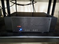
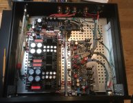
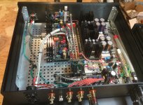
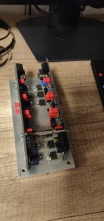
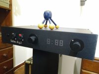
I have finally finished testing all the components for my DCG3 and found time to box them
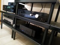
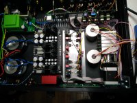
Here are a few pics of the penultimate state while it is burning in, and I have a chance to listen to lovely preamp.
At the moment the input it is my old Yamaha cd player (refuses to perish) into Sennheiser HD380pro headphones. How does it sound? Well, remarkable detail and I was hearing things from the recordings that I hadn't noticed before. Dead silent even at high volume with no input.
For the first half hour or so the mids and high end were very forward, especially mids, and bass was kind of weak. Nonetheless, after a little while the highs calmed down and the mids receded, the low end made it presence known, and the soundstage opened up. Beautiful.
I was listening to the Te Kanawa/Popp/von Stade recording of Figaro, and my wife looked at me quizzically because my eyes were misting up. Ahh, she knew.
Big thanks to Salas and Tea Bag for making the design and hardware available. A prime piece of kit and a keeper.
I have finally finished testing all the components for my DCG3 and found time to box them
Here are a few pics of the penultimate state while it is burning in, and I have a chance to listen to lovely preamp.
At the moment the input it is my old Yamaha cd player (refuses to perish) into Sennheiser HD380pro headphones. How does it sound? Well, remarkable detail and I was hearing things from the recordings that I hadn't noticed before. Dead silent even at high volume with no input.
For the first half hour or so the mids and high end were very forward, especially mids, and bass was kind of weak. Nonetheless, after a little while the highs calmed down and the mids receded, the low end made it presence known, and the soundstage opened up. Beautiful.
I was listening to the Te Kanawa/Popp/von Stade recording of Figaro, and my wife looked at me quizzically because my eyes were misting up. Ahh, she knew.
Big thanks to Salas and Tea Bag for making the design and hardware available. A prime piece of kit and a keeper.
Attachments
Hi Salas,
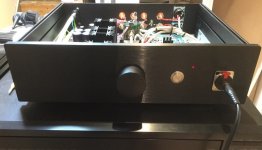
Thanks, it really was a pleasure to build, though I am not a fast builder. The 15V regulator for Meldano’s 72320 muses attenuator, and the cd4017 based channel selector (thanks to member Mooly) were my first attempts at vero type board circuitry and there were some errors along the way... Also borrowed some grounding ideas from member Bonsai’s comprehensive guides (thanks Andrew).
I opted for bc327-40 (Diotec) based on feedback from other members. I am really curious to see how the sound will mature after 40 or 80 hours of playing time.
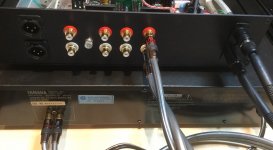
The xlr output is strictly non-balanced; just provides options for cabling.
Thanks again Salas, I am really enjoying the DCG3!
Thanks, it really was a pleasure to build, though I am not a fast builder. The 15V regulator for Meldano’s 72320 muses attenuator, and the cd4017 based channel selector (thanks to member Mooly) were my first attempts at vero type board circuitry and there were some errors along the way... Also borrowed some grounding ideas from member Bonsai’s comprehensive guides (thanks Andrew).
I opted for bc327-40 (Diotec) based on feedback from other members. I am really curious to see how the sound will mature after 40 or 80 hours of playing time.
The xlr output is strictly non-balanced; just provides options for cabling.
Thanks again Salas, I am really enjoying the DCG3!
You are welcome. Best thing is you managed quietness in your build. Tone will mature a little further with more charge / recharge cycles on the electrolytics in the next days.
P.S. If you are ever going to use the two line outputs at the same time, I recommend you wire one of those not from the one next to it but from the HP output on the board. Though with one own equal 49.9Ω resistor to the R15 buffering the main line output. In series with signal hot. So the two utilized parallel outputs won't interfere enough when hooked up to equipment down the chain. Say two power amps for biamping speakers, or a main power amp and a subwoofer's back plate amp etc.
P.S. If you are ever going to use the two line outputs at the same time, I recommend you wire one of those not from the one next to it but from the HP output on the board. Though with one own equal 49.9Ω resistor to the R15 buffering the main line output. In series with signal hot. So the two utilized parallel outputs won't interfere enough when hooked up to equipment down the chain. Say two power amps for biamping speakers, or a main power amp and a subwoofer's back plate amp etc.
- Home
- Source & Line
- Analog Line Level
- Salas DCG3 preamp (line & headphone)