Twisted pairs to keep the loop area narrow. Else all the area until signal return is susceptible to interference. One can be pseudo i.e. grounded on one side only. When your DCG3 board is not the newest with separated channel ground lanes that is.
As you are in open plan status right now, and that's handy, try it to play for no hum in the end. So you can easily change details if there is any. That test should include the volume pot. Its metal body part should be grounded as well.
The selector has DCin too. You can steal raw DC under a DCSTB's reservoir capacitor instead of AC if it will be quieter.
The aluminum base plate should be grounded to one DCG3 signal ground also.
Gain setting R and subwoofer output
I want to lower my gain from 3x with the 1kR. My store has some nice resistors PRP PR9372 Series Metal Film resistors, but not in 499R. Nearest are 470 or 510. Is it ok to use one these values? Obviously I wont hit exactly 2x gain but I didn't know if the gain had to be a whole number.
And I also wish to take a feed to a subwoofer. I read I can either bridge R15 49.9R and then add 49.9R series to all RCA out....or just Y the original stereo pair as the DCG3 can provide the drive.
In both instances I need to use 10k summing on both new stereo pair to create mono sub feed? I saw one reply mentioned 100kR summing.
It is to feed a REL subwoofer. I do not know its input impedance.
Regards
James
Use the 510R. Gain will practically be X2. Keep in mind that lower gain, probably better for your particular amp's sensitivity, also prefers sensitive enough headphones if you will be using any.
The DCG3 can provide the drive but put resistors to avoid interference between the equipment connected on those outputs. Bridge R15 so all outputs will have equal 49.9R buffering resistors to RCA hot. 100R makes even better buffering when the interconnects are rather long.
About channels summing to a REL sub practicalities I don't know, but a passive summing network should be of at least ten times lower output impedance to the input impedance it will drive I would suppose. To also have the summing network nearest to that input could have benefits against interference through cables I would have thought.
Find your REL's input impedance in literature or measure it across its input connector.
Thus very low impedance. DCG3 will handle it though, along with the task of driving the main amp. Use 220R in series with each channel's output RCA to the REL. Instead of 49.9R. Those will make your sum source impedance. Then interconnect cables to a Y adapter at the REL's mono input.
Ok, like an idiot I connected 34VAC to the input of my iSelect rather than 17VAC. The LED came on for a short while and then went out before I realised what I'd done. What have I likely trashed, just the 7812?
0V -> Anode D3 - 8V
0V -> Cathode D1 (input to LM7812?) - 24V
0V -> R1 (out of LM7812) - 0V
0V -> Anode D3 - 8V
0V -> Cathode D1 (input to LM7812?) - 24V
0V -> R1 (out of LM7812) - 0V
You could have only burned the LED but the 7812 is possible too. When with 17VAC AC-IN probe for rectified DC between the DC-IN V+0V connector pads. For the 7812 output probe between the 0V Vreg Out connector pads. Black probe to 0V in both cases.
Correct readings should be +24V and +12V DC. If you got the +24V but not the +12V change the 7812. If you haven't got the +24V check the diodes with the DMM's diode mode, also check the reservoir capacitor C1 for bulging top. Because its 35V rated and it should have seen 48V during the mishap. The LED check it briefly with a 9V battery or with your DMM's diode checker if it puts out >2V test voltage.
Did you hear any relays clicking during the mishap?
 I'll order a new 7812.
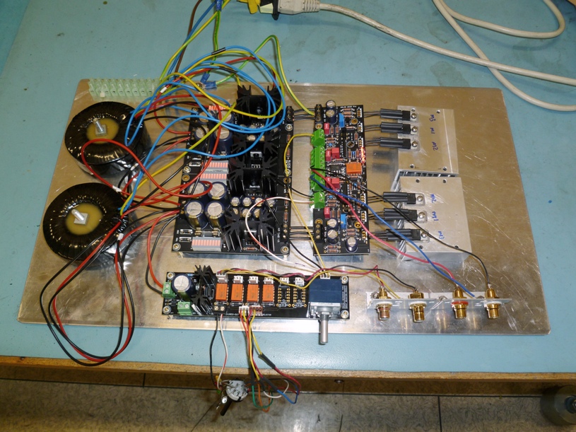
- Home
- Source & Line
- Analog Line Level
- Salas DCG3 preamp (line & headphone)