I checked R8 and it is correct. Then I replaced all the transistors. I still get .04 volts, exactly as before, so I am baffled.
Did you also check most other resistor values are correct? The Dales can be read by their codes instead of one leg lifted for correctly measuring them in places that they would not show nominal. Important is to read some circuit voltages. Like from Q1 Q2 collectors and M1 drain to ground. Also measure M1 M2 M3's gate to source voltage and R3's mV drop across it. Those should give us a clue.
I plan on building the DCG3 kit exactly as designed to thoroughly evaluate, but can't help but think it could use a SIT in a critical position. Anyone had the same idea, or done some sims, maybe a THF-51S could be made to work?
I have a couple of those left over from another project.
I have a couple of those left over from another project.
Those SIT are N-type aren't they? Here the V MOS are P-type. Also having much less Cgs capacitance. You could see the DCG3 as inspiration for a turned around schematic with PJFET input pair and maybe add buffer stage to properly drive SIT cascode for comparable THD. But you could not drop in some TOKIN as it is. An output stage CCS like the DCG3's would flatten the transfer on SIT triode like curves though.
Hi Salas,
I checked that all the resistor values are correct. I measured, as you suggested. I got .106 volts across R3 on the left channel vs .831 on the right. I got .650 on M1's drain on the right vs. -5.881 on the left. I got .725 on M2's drain on the right vs. -17.26 on the left. M3's gate to source voltage is -.04 volts on the left and .083 volts on the right. Something is wrong. I wish I understood more. I really hope it is fixable - I'd love to hear what others have enjoyed! I work in a high end stereo shop and I'd love to get a bit closer to the sound quality of those pieces I can't afford to buy, plus the satisfaction of successfully completing something! Thank you,
Mark
Something is wrong.
Mark
Something is very wrong indeed. From those oddball check voltages on both channels, that they don't even follow each other, I have a suspicion that some basic thing is wrong like a PSU polarity connection might been reversed somewhere. Or some rail is down or a crucial joint isn't done well like beardman wrote.
P.S. Power both sides as in final config to check rail polarities and their values on all the DCG3's input power terminals.
Apologies if this has been asked before but can the DCG3 be used for fairly efficient (90dB, 4 ohm) room speakers? Listening levels would be moderate loudness only
Thanks
i would look into the aleph series topology for something ressembling to a power amp version of this pre.
Alternatively, You could try to put a firstwatt f4 after this pre to keep some of the caracteristics of it in the final sound, like i plan doing.
Last edited:
Something is very wrong indeed. From those oddball check voltages on both channels, that they don't even follow each other, I have a suspicion that some basic thing is wrong like a PSU polarity connection might been reversed somewhere. Or some rail is down or a crucial joint isn't done well like beardman wrote.
P.S. Power both sides as in final config to check rail polarities and their values on all the DCG3's input power terminals.
My R3s are 150R> Something is wrongg in the power supply. Each channel puts out about 17.45 volts between the ground and one phase, but - 6 volts between ground and positive in the right channel, and .75 volts between ground and negative on the left channel. Does this indicate a place to check? I also notice the right LED bank goes out immediately when I cut power, on both channels.
Disconnect the supplies from the preamp's board now. Power on again to measure them on their own. As you know the DCSTB board has two units with a triple output terminal on each corner. Normally they measure at somewhat higher than +17V and -17V in respect to zero when the meter's black probe is put in the middle screw and the red touches the V+ or V- labeled screws of those terminal connectors. Also as +34V to +35V when the red is on the V+ and the black on the V- screw of one same triple terminal.
If they do not read as above, in one or both units, first see if you got some NPN/PNP type mixed for Q1 Q2 Q3 Q4 and/or an orientation is wrong for Q2 Q4. Stuffing mistakes are easier to happen in mirrored layout PCBs like this one. Read their silkscreen positions and face prints with the help of a torch light to confirm. If all that looks correct, now measure Vbe for all mentioned transistors to see if there are any bad ones. Around 0.6V to 0.7V should be a normal indication. Also measure the mV drop across R1's and R2's pins on each side. Those will indicate the current through the LED bar references to see if they are about the same and enough (5mA +/- 20%).
If they do not read as above, in one or both units, first see if you got some NPN/PNP type mixed for Q1 Q2 Q3 Q4 and/or an orientation is wrong for Q2 Q4. Stuffing mistakes are easier to happen in mirrored layout PCBs like this one. Read their silkscreen positions and face prints with the help of a torch light to confirm. If all that looks correct, now measure Vbe for all mentioned transistors to see if there are any bad ones. Around 0.6V to 0.7V should be a normal indication. Also measure the mV drop across R1's and R2's pins on each side. Those will indicate the current through the LED bar references to see if they are about the same and enough (5mA +/- 20%).
Build Progress
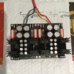
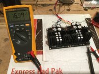
Okay! Making some progress with my build and thought I'd share some pictures.
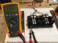
Just finished the DCSTB and did some testing. Still working on heat sink arrangements for the DCG3, so these tests were no load.
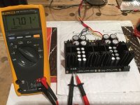
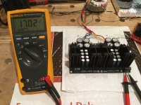
The LED bars look really cool! Input is 18V-25VA for this trial, and voltages drop about 40 mV over 3 minutes or so and then stabilize at the levels shown. With 50 VA per side (secondaries in series) the output is about 60 mV higher. I think (hope?) this is a good result.
Looking forward to getting it all together, and I hope it will turn out as well as other builds in this thread. Many thanks to Salas and Tea for making this kit available!
Okay! Making some progress with my build and thought I'd share some pictures.
Just finished the DCSTB and did some testing. Still working on heat sink arrangements for the DCG3, so these tests were no load.
The LED bars look really cool! Input is 18V-25VA for this trial, and voltages drop about 40 mV over 3 minutes or so and then stabilize at the levels shown. With 50 VA per side (secondaries in series) the output is about 60 mV higher. I think (hope?) this is a good result.
Looking forward to getting it all together, and I hope it will turn out as well as other builds in this thread. Many thanks to Salas and Tea for making this kit available!
Attachments
-
 3DD7F0FC-F0AF-4D79-A048-EC6BC63E0817.jpeg306.6 KB · Views: 481
 -
 18F74185-0622-4292-8E03-97CBDE3A8E71.jpeg128.8 KB · Views: 523
 -
 DA1EBECE-1B77-440A-9F65-14EA1F9DE711.jpeg126.2 KB · Views: 497
 -
 5A2A8168-C450-421B-A107-E9532D4939EF.jpeg130.5 KB · Views: 452
 -
 13BC2A51-72BE-4535-BA83-822DFE6FA246.jpeg133.7 KB · Views: 459


- Home
- Source & Line
- Analog Line Level
- Salas DCG3 preamp (line & headphone)