I bought some connectors like these : 1PC Flexible Winding Connector Motor Shaft Coupling Stepper Motor Coupler ATRM | eBay
for 6mm and I had some spares from previous builds.
You can also use something like this : Aluminum 260mm Volume potentiometer extension rod shaft /signal selection lever | eBay
for 6mm and I had some spares from previous builds.
You can also use something like this : Aluminum 260mm Volume potentiometer extension rod shaft /signal selection lever | eBay
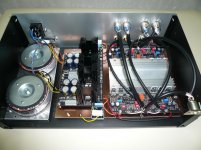
I just populated all parts. It looks good so far, no smoke no smells.
There is one newbie's question. I read the instruction Salas wrote about adjust DC offset. It says "short the signal inputs". Does it means that I need to connect "in" and "G" with wire first, then adjust the DC offset?
There is one newbie's question. I read the instruction Salas wrote about adjust DC offset. It says "short the signal inputs". Does it means that I need to connect "in" and "G" with wire first, then adjust the DC offset?
Attachments
Yes, shorting the input means In-->G with a wire first. Not very important in this build, because its low gain and generally steady, but good general practice. Especially before put in a grounded box.
Its to avoid the chance of some noise being picked up by its hi-Z open input, and after amplified also, to interfere at the output making it look jumpier than real. Not to trim compensate for "ghosts".
Its to avoid the chance of some noise being picked up by its hi-Z open input, and after amplified also, to interfere at the output making it look jumpier than real. Not to trim compensate for "ghosts".
Finally getting around to completing my balanced build. Two DCG3 boards each powered by 1/2 DCSTB each with a transformer.
A few questions:
1)From the DCSTB outputs + G _ , should I run separate wires to each of the DCG3 + G _ points ie 6 wires out or should I take 3 wires and then daisy chain to the next? I think I read that 6 wires is the way to go but cant remember.
2)I will install two CL60's to chassis, one for each channel. Should I connect the one end of the CL60 to DCSTB G or to the PCB G? If PCB G then which one?
3)I could also connect a link to the two outer G power points on the DCG3 and connect the G wire from the DCSTB to the center of this link and also connect the CL60 at this point, if this is technically superior. XLR pin1's are planned to be connected to the chassis.
Thanks. nash
Hi Nash,Finally getting around to completing my balanced build. Two DCG3 boards each powered by 1/2 DCSTB each with a transformer.
A few questions:
1)From the DCSTB outputs + G _ , should I run separate wires to each of the DCG3 + G _ points ie 6 wires out or should I take 3 wires and then daisy chain to the next? I think I read that 6 wires is the way to go but cant remember.
2)I will install two CL60's to chassis, one for each channel. Should I connect the one end of the CL60 to DCSTB G or to the PCB G? If PCB G then which one?
3)I could also connect a link to the two outer G power points on the DCG3 and connect the G wire from the DCSTB to the center of this link and also connect the CL60 at this point, if this is technically superior. XLR pin1's are planned to be connected to the chassis.
Thanks. nash
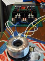
Here is what I did - see pic.
1) Daisy chain the two channels. The GND of each DCG3 is common for both onboard channels so no need to connect them again with an external wire. Just two wires for + and - from ane channel to the other and then to DCSTB provided it is lockated close to the DCG3.
2) You will only need one CL60 per DCG3 board. It could be connected like my ground lifters - the rectifier bridge with the power resistor and the cap.
3) XLR pin 1 is connected to chassis in my construction and it works. But on second thought it may be not optimal solution because this is not a true differential amp and I expect signal to pass through the GND lifter/CL60. I'm going to return pin 1 to DCG3 GND. This would not affect channel GND separation in my system because source GND is allready common for both channels and power amps are monos with XLR pin 1 to chassis.
I hope that helps!
Attachments
the signal should not pass through the safety connection to chassis.I expect signal to pass through the GND lifter/CL60
The signal should pass along and back through a Signal PAIR. Signal should never go anywhere else.
This is true for differential amps. Here we have two indepented lines that do not amplify the difference of the signals applied in their inputs but just amplify the antiphase signals they get from the source. In differential amps the circuit ground stays out of the line. In the application discussed here the circuit ground is the returning path af the signal as with all SE circuits
Hello!
Salas, I'm thinking about to try some better resistors like Shinkoh that I like very much in my DCB1, but are expensive. What resistors do you think are more critical in the signal path? (R1, R15 and RZJ, evidently)
Thanks!
Ignacio.
R6, R7 (feedback) for sure are important
R4, R5 (gate stoppers) are in the signal path also
This is true for differential amps. Here we have two indepented lines that do not amplify the difference of the signals applied in their inputs but just amplify the antiphase signals they get from the source. In differential amps the circuit ground stays out of the line. In the application discussed here the circuit ground is the returning path af the signal as with all SE circuits
Can alternatively lift from GND and connect the phase channel amps R7 feedback returns together
This is true for differential amps. Here we have two indepented lines that do not amplify the difference of the signals applied in their inputs but just amplify the antiphase signals they get from the source. In differential amps the circuit ground stays out of the line. In the application discussed here the circuit ground is the returning path af the signal as with all SE circuits
Kostas, I thought that you mentioned that you had a balanced connection going into your DCG3 from your DAC. In which case you should have signal between pins 2 and 3 only, not between pin 2 and pin1 and pin 3 and pin 1, since pin 1 is only the shield. I am referring to the XLR plug that plugs into the XLR connector of the DCG3.
nash
Yes, I ought to test this at some point. It would change the way I can connect DCG3 for balanced or SE mode though.Can alternatively lift from GND and connect the phase channel amps R7 feedback returns together
SLB is connected midway to the wire from DCG3 to DCSTB2) You will only need one CL60 per DCG3 board. It could be connected like my ground lifters - the rectifier bridge with the power resistor and the cap.
Thanks for responding Kostas.
So is your SLB connected to the DCSTB G point? I see that it is next to it.
nash
DAC output is balanced but circuit GND is connected to chassis by default and consequently so is pin 1 coming out from it though I suspect the sound card incorporates some kind of SLB too. Pin 2 and 3 carry the signal. Typical so far. Now, DCG3 input pin 1 could be connected to chassis or circuit GND without altering the grounding scheme of the DAC - sound card. Actually, when DCG3 runs on balanced mode it doesn't need the SLBs. It needs them only in SE mode. But even in balanced mode - if we don't do the R7 modification - DCG3 works in SE mode and then pin 1 is in the circuit.Kostas, I thought that you mentioned that you had a balanced connection going into your DCG3 from your DAC. In which case you should have signal between pins 2 and 3 only, not between pin 2 and pin1 and pin 3 and pin 1, since pin 1 is only the shield. I am referring to the XLR plug that plugs into the XLR connector of the DCG3.
nash
")

- Home
- Source & Line
- Analog Line Level
- Salas DCG3 preamp (line & headphone)