The ground plane is just a very wide trace that happens to cover the whole PCB.
If you have a separate ground trace on another layer then you need to connect these somewhere.
That chosen location must not force a trace to carry two different AC currents that could cause an undesired interaction between the voltage drops.
__________________
Thanks ! Very kind of you Andrew to answer my quistions...
")
But my answer was, if this GNDplane should be connected to GND on PCB
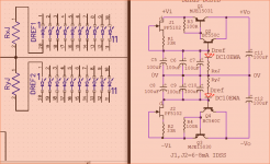
Anyway, Salas do the diodes inside DC10EWA have to be connected in series ?
Jesper.
Attachments
What is gnd plane in your speak? You mean the metal box? Because you don't picture a three layer board with a ground pane layer. Yes zig zag series given the bar package.
Thanx!
Gnd plane, is what i allways thought a place/area on the pcb, with pure copper.
On the bottom on you're pcb, there is what i call a gnd plane!
Jesper.
Attachments
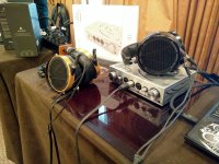
Meanwhile the preamp is doing great in the house system as a line pre. It made a pitch stop at the bench first of course. I changed its long signal wires type and their grounding a bit.
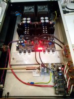
Bass drive is power drill like but in the mids and highs its soft and high resolution at the same time. Tea & Tham are right it can startle you at times with presence and 3D, Michael is right this one is better than the betas he brought over before. BTW the box sinking with the 10mm Alu bar in-between had only 38C on the output semis with the box open. If a normal side sink is enclosed and not well ventilated from under and above usually fares worse.
Bass drive is power drill like but in the mids and highs its soft and high resolution at the same time. Tea & Tham are right it can startle you at times with presence and 3D, Michael is right this one is better than the betas he brought over before. BTW the box sinking with the 10mm Alu bar in-between had only 38C on the output semis with the box open. If a normal side sink is enclosed and not well ventilated from under and above usually fares worse.
Attachments
Thanx!
Gnd plane, is what i allways thought a place/area on the pcb, with pure copper.
On the bottom on you're pcb, there is what i call a gnd plane!
Jesper.
Alright so you mean the fat common ground trace. Ground plane they call an uninterrupted field of copper as big as the circuit where they refer each and every local ground point directly. You mean if you got to connect that trace to the chassis? I do at the pot's common through the wire shields but every system is not the same for grounding as a whole. My friend had it lifted & also had the right channel's coax shield in pseudo i.e. one way connected.
Hi here
So English (espcially technichian's) is not my native langauge ...
I will try to explain as good as i know now :
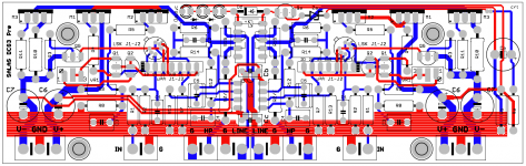
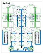
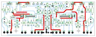
In my world, a groundplane is, as Salas explained here so you mean the fat common ground trace. Ground plane they call an uninterrupted field of copper as big as the circuit where they refer each and every local ground point directly. The picture attached, shows a red groundplane at my pcb. My quistion is then, if i have to connect the GND connection(s) on the pcb to that groundplane ? At bottom of my pcb, there are 8 GND pattern's.
About the connection's from chassis, volumepot etc... i will make a star connection, when time comes i think. Eventually the most correct thing (As i learned it) is to allways only connect shield at one end on coax cables, for avoiding "antenna distortion".
Well... i think it's nice that you guy's try to answer my quistion's, eventhrough i am not that good a writer (In English). Thank you for that.
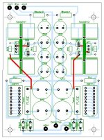
Salas, would you care to share the sizes, and layout of the PSU pcb's ?
I attached a picture of my ongoing PSU layout.
Jesper.
Alright so you mean the fat common ground trace. Ground plane they call an uninterrupted field of copper as big as the circuit where they refer each and every local ground point directly. You mean if you got to connect that trace to the chassis? I do at the pot's common through the wire shields but every system is not the same for grounding as a whole. My friend had it lifted & also had the right channel's coax shield in pseudo i.e. one way connected.
So English (espcially technichian's) is not my native langauge
...I will try to explain as good as i know now :
In my world, a groundplane is, as Salas explained here so you mean the fat common ground trace. Ground plane they call an uninterrupted field of copper as big as the circuit where they refer each and every local ground point directly. The picture attached, shows a red groundplane at my pcb. My quistion is then, if i have to connect the GND connection(s) on the pcb to that groundplane ? At bottom of my pcb, there are 8 GND pattern's.
About the connection's from chassis, volumepot etc... i will make a star connection, when time comes i think. Eventually the most correct thing (As i learned it) is to allways only connect shield at one end on coax cables, for avoiding "antenna distortion".
Well... i think it's nice that you guy's try to answer my quistion's, eventhrough i am not that good a writer (In English). Thank you for that.
Salas, would you care to share the sizes, and layout of the PSU pcb's ?
I attached a picture of my ongoing PSU layout.
Jesper.
Attachments
Hi here
So English (espcially technichian's) is not my native langauge
I will try to explain as good as i know now :
In my world, a groundplane is, as Salas explained here so you mean the fat common ground trace. Ground plane they call an uninterrupted field of copper as big as the circuit where they refer each and every local ground point directly. The picture attached, shows a red groundplane at my pcb. My quistion is then, if i have to connect the GND connection(s) on the pcb to that groundplane ? At bottom of my pcb, there are 8 GND pattern's.
About the connection's from chassis, volumepot etc... i will make a star connection, when time comes i think. Eventually the most correct thing (As i learned it) is to allways only connect shield at one end on coax cables, for avoiding "antenna distortion".
Well... i think it's nice that you guy's try to answer my quistion's, eventhrough i am not that good a writer (In English). Thank you for that.
Salas, would you care to share the sizes, and layout of the PSU pcb's ?
I attached a picture of my ongoing PSU layout.
Jesper.
We can't know what will be the best tactic for grounding in each one's build. Not all peripherals inside and outside will be the same. Its a hands on thing and you are a diyer. You will find your best hum/buzz result for your own configuration build in your audio system because you can experiment. You are already making a board alone which is untested. So who knows. It may just oscillate before even allowed thinking grounding stuff. There are four people that have built it, two of them even with greater personal variations than yours up to now. Michael Tea Tham me. We are not having real practical problems as reported. But this is a very small group statistic. We don't know if the ground trace will work better for most systems when cut in the middle or the relay to be resting at gnd when idle for instance. Those are things that did not affect our experience. But may prove better done otherwise for others. There is ability to mod those areas as is. I am sure we will see people even skipping the relay and jumpering over because they have a capacitor coupled input amp or never power up in unorthodox sequence etc. We will also see people skipping the DC servo because they will feel secure with the circuit's own DC drift when having a coupling cap and DC output protection in their amps. First round leaves space to explore always. I would bring series to gate resistors closer to Jfets and Mosfets in your pcb if in your shoes BTW.
I would bring series to gate resistors closer to Jfets and Mosfets in your pcb if in your shoes BTW.
Yes... Thx... I see what you mean! -I will correct that.
Anyway i will do the PSU first i think, and when that is tested, i will do the Preamp pcb...
We can't know what will be the best tactic for grounding in each one's build. Not all peripherals inside and outside will be the same. Its a hands on thing and you are a diyer. You will find your best hum/buzz result for your own configuration build in your audio system because you can experiment. You are already making a board alone which is untested. So who knows.
That's the thrill of it!
Uhh... ...Well, back many year's ago i did the Pumpkin Preamp. I could never adjust the thing completely. If it was my back then clumsy pcb, or if it was the lack of a descent psu i don't know, and proberly never will find out. It must be part of game
Jesper.
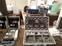
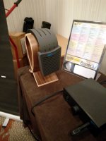
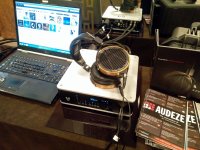
I went to a local cans annual show today. Listened to some. There was even an importer of mainly DJ and in-ear stuff that his company is named Salas Headphones
Some pics I took with the mobile: Audeze, Final, Ergo, AT700X, RHA, and an immaculate AKG K1000 (not produced in many years). Some big name companies were absent.
Some pics I took with the mobile: Audeze, Final, Ergo, AT700X, RHA, and an immaculate AKG K1000 (not produced in many years). Some big name companies were absent.
Attachments
-
 IMG_20161009_170158.jpg398.4 KB · Views: 375
 -
 IMG_20161009_164202.jpg676.5 KB · Views: 422
 -
 IMG_20161009_164128.jpg556 KB · Views: 427
 -
 IMG_20161009_162945.jpg682.1 KB · Views: 408
 -
 IMG_20161009_162617.jpg726.6 KB · Views: 426
 -
 IMG_20161009_162353.jpg660.7 KB · Views: 448
 -
 IMG_20161009_170341.jpg564 KB · Views: 497
 -
 IMG_20161009_161317.jpg525.2 KB · Views: 654
I went to a local cans annual show today. Listened to some. There was even an importer of mainly DJ and in-ear stuff that his company is named Salas Headphones
Are you co-founder of that company?
Are you co-founder of that company?
By no means. I just found it funny there was a cans importer company named like that. I asked the owner guy and he said that his company's name comes from combining first letters of his name and his surname. Mystery solved
I would bring series to gate resistors closer to Jfets and Mosfets in your pcb if in your shoes BTW.
Hi.
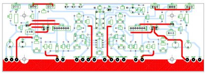
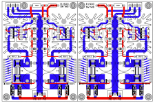
Does this layout look any better Salas ?
Btw. : Can you post the PCB layout of the psu?, like you did with the preamp pcb?
Good evening all. Jesper.
Attachments

Hi.
Does this layout look any better Salas ?
Btw. : Can you post the PCB layout of the psu?, like you did with the preamp pcb?
Good evening all. Jesper.
Looks better.
Of course, this is an open info design for diyers. Who wants get an official board is absolutely voluntary. I always help & support everybody diyer to best of my time and ability even when with an untested hardwired build.
Attachments
Salas, hope you feel better soon
Thanks for sharing all.
The preamp circuit, is kind of the edge which i can do by handdraw i think.
Actually consider to buy them, when they will be avalible?
The PSU(s) i can do, no problem handdrawn.
I am looking forward for the "official" bom, and notes etc...
God bedring Salas.
Rgds; Jesper
Thanks for sharing all.
The preamp circuit, is kind of the edge which i can do by handdraw i think.
Actually consider to buy them, when they will be avalible?
The PSU(s) i can do, no problem handdrawn.
I am looking forward for the "official" bom, and notes etc...
God bedring Salas.
Rgds; Jesper
when they will be avalible?
Whenever Tea is able. Me I just owe the pdf and there is nothing more for now. I want to revisit the V1.2R PSU for making it more accessible as the few makers of it hold it up very highly and I have for months now those low noise ZTX transistors I want to experiment for a phono with. Maybe I can combine a junior semis dcg3 topology as second stage for selectable cartridge gain
- Home
- Source & Line
- Analog Line Level
- Salas DCG3 preamp (line & headphone)