Looking for a little insight, When i connect my DCG3 preamp build directly without a pot, I loose a lot of volume /gain. I am currently using a 15v ac x 2, until the Antek become available. The highs also seem muted when compared to when i connect the source directly to the amp. Has any one else had this experience?
Maybe you experience oscillation when without a pot. Assuming everything else is correct. You shouldn't but its too complex to say offhand for some experimental setup. Try 4.7K series resistors on your DCG3 input connectors for now to buffer the whole input wiring better. Your now trafo is border spec for the DCSTB also. Measure its rails DC when loaded by the DCG3.
Hmm! I run my DCG3 without input pot too. I don't face frequency response or gain related probems but, I have a hiss noise, a 10kHz peak. Not anything to make me fix it as it is just a whisper on my sensitive speakers yet, good to know if it could be removed. Do you thing it has anything to do with input buffering?
Edit; I just saw iancortez's reply. I did a quick google search the other day and there where two explanations that cought my attention. One is related with Q1 Q2. I see some builders to thermocouple them. I haven't. Should I? The other is stray capacitance between output mosfets back plates and grounded heatsink(?).
Edit; I just saw iancortez's reply. I did a quick google search the other day and there where two explanations that cought my attention. One is related with Q1 Q2. I see some builders to thermocouple them. I haven't. Should I? The other is stray capacitance between output mosfets back plates and grounded heatsink(?).
Last edited:
I also tried a 50K pot need to order 20k, there was no difference in audio level, the output from the preamp is always lower than the source. the rail voltages are -17.15 16.96 and 16.98 -16.94,
Still do try those 4.7k directly on the PCB line in connectors just in case. Some other problem must be at play if no change then. Build level problem. Maybe you misplaced R6 for R7? The rail voltages are sufficient. With more Vin-Vout from 18 VAC trafos there is better performance but your rails are still around 17VDC for a basically correct test. The DCSTB LED packs look bright enough, right?
*Don't place the audio system in danger. Even if not having gen & scope use 300HZ sinewave test signal from some digital device and a DMM in ACV mode to measure in vs out while debugging.
Hmm! I run my DCG3 without input pot too. I don't face frequency response or gain related probems but, I have a hiss noise, a 10kHz peak. Not anything to make me fix it as it is just a whisper on my sensitive speakers yet, good to know if it could be removed. Do you thing it has anything to do with input buffering?
Edit; I just saw iancortez's reply. I did a quick google search the other day and there where two explanations that cought my attention. One is related with Q1 Q2. I see some builders to thermocouple them. I haven't. Should I? The other is stray capacitance between output mosfets back plates and grounded heatsink(?).
I can't say if you can eliminate it with a bit more source resistance because its not an oscillation. You have a more extensive double build for balanced and it could be picking little something from the more wiring or the ground. Try 1K in series at your line in connectors on the PCBs. Move your line input wire hot on the resistor for a test. If you had oscillation you would have known it. Scoped sinewave would be thick and hazy, FFT would have gone wild full of peaks, your sound would have been ruined completely in all sonic parameters and nuisance noises would have manifested. I did not thermocouple anything in my proto just to make sure and I did not measure any bumps in the noise floor. It was even.
Thanks Salas! Sound is crystal clear. Hiss noise comes definately from DCG3 and is also there with inputs shorted to ground. The basic ground scheme is very simple but I have installed parallel XLRs and RCAs I/O and the only thing I can think at the moment is a different connection of the multiple coaxials. I will try it and report back.
1V RMS = 0dBVOops! I don't feel very comfortable when the discusion comes to dBs.I 'll try to post a -non calibrated- FFT later.
Having a problem with the negative side of my DCSTB power supply. Both the positive and the negative voltage match when I use a Variac up to 15.25 volts PS output voltage – measured across a 150 ohm WW resistor load. The positive side levels off at 17.1 at full wall voltage and the negative side start climbing to 29 volts at wall voltage. This symptom happed using the original parts from the kit.
I replaced the original negative power supply FETs, and transistors parts from the kit I purchased with: Digikey parts: MJE15030GOS-ND, BC560CTACT-ND, PF5102-ND, 754-1176-5-ND
I swapped out the original parts with the above parts and nothing changed – still 29 volts at the negative side output. The parts positions are all correct.
I also replaced the LED bar graphs, both positive and negative with 754=1176-5-ND. The positive LED bar graphs light up at full voltage. The negative bar graphs do not light up. I have checked each LED with a 12V battery and can get light at each LED on the negative side.
I purchased a batch of PF5102 and measured them for Id with M3 Semiconductor Analyzer. They all measure between 5.5 & 8.00. I am using a PF5102 that measures close to 8.00 in the negative PS.
I toothbrush scrub the boards down with 99% alcohol.
I wonder if you have a suggestion how I can tame the negative side of this DCSTB.
Attachments
In normal operation first they must light up, second their operating current must be comparable to those at the positive side. In that case the mV drop across R2 indicates the current that runs through the negative LED bars. R2 is the J2's degeneration resistor and its value can be even changed to manipulate the current for LEDS VF even when not having a matched to J1 IDSS sample for J2. When the negative bars are dark Q4 is probably out so Q3 is uncontrolled and just passes near Vin. Also can happen if RyJ has too high value by mistake or missing.
Just a hint for further problem solving: See post #829
I had mixed up the Q1/Q3 on the other channel and measured too high voltages.
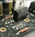
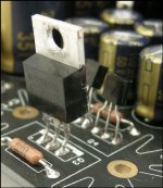
Also such a misplacement can be the answer if its not due to some part is broken. But in this case the photographs show the proper Q3 type.
I should mention, I bought the double power supply option. I have one working DCSTB power supply. Parts position was the first thing that came to mind so I have looked at this after taking a step away - a few times. About the Digikey part BC560CTACT-ND Have I made an error in ordering this specific part?
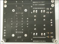
It is time to place a summary of my build. I already published my first 4 hours listening session experiences about 2 month ago and now it is fully finished product. Just for general overview: it is no any deviation from Salas's manual and I assembled it with x3 gain and 160mA bias. Please see high res images attached.
Last edited:
- Home
- Source & Line
- Analog Line Level
- Salas DCG3 preamp (line & headphone)