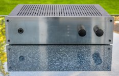
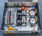
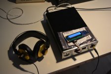
Interesting compact combo. BTW matched 2SK170BL pairs can alternatively go in the UPA pads too. There are DGS-SGD designations on the silkscreen to guide. No need to bend pins if there will be no thermal coupling. They will just face inwards and outwards. The servo tracks DC offset so it can be practically feasible. Don't apply >18V rails when using a servo op-amp that can not accept it. You could check the PSU before connecting to the system with 150 to 200R 5W dummy load resistors but its doubtful that it will lose enough output because it has low output impedance. If its because the LEDS and/or JFET CCS tolerances in the PSU went enthusiastic try higher source degeneration resistors. R1 & R2 in DCSTB are 33R. Try 100R. Less current will run through the LEDS to tame their combined VF.On saturday I finally receive Chines aluminum case...
It turn out to be a little small as I didn't have all components in my hand when I was ordering the case...
so...it's compact...low or no heat dissipation...maybe it will melt down
will see, will it do the trick
so this is Jlsounds USB/I2S/AK4490 DAC with Salas DCG3 combo
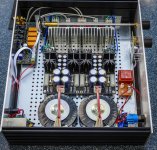
still in progress...
was thinking to go with jfets K170 but the layout is not design for them, so I would have to band their legs, which is a little complicated
so at the and I'm going with ''stock' version
I have a little desbalanced voltage on power supply on one channel, but Salas say not to worry about it..so I will not...( one side have 18.30 on +/- but the other one have like 18.21 and 18.39 V)...I'm not shure is it 18 or 17V without the load...
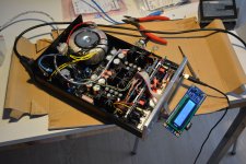
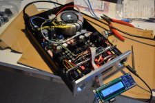
So, here are some pictures of work in progress, will get back and report how it sound, once I finish it
DCG3 Build Photos
Just finished a DCG3 Build in a Galaxy Enclosure!
The sound is quite incredible - I've never heard anything quite like it!
A very big Thank You to Salas for sharing such an amazing piece of work, and to Tea for putting it into a kit that fits together like a jigsaw!
If you are still just thinking of building one then please take my advice and do it, you will be amazed too!
Attachments
Last edited:
I've been always fascinated by small crowded boxes. To my eyes this is an excellent build! I think heat dissipation is marginally OK.
jea...I think it will do...
I have some Pass diy aleph preamplifier's and amplifiers so I'm not afraid of some heat

Outstanding build I say....
What is the voltage used to power the dac ?
The voltage for DAC is 5V
have 2 x 6V AC and then via some LT1083 regulator (12$ from ebay) to get around 5V for DAC and I2S board
Interesting compact combo. BTW matched 2SK170BL pairs can alternatively go in the UPA pads too. There are DGS-SGD designations on the silkscreen to guide. No need to bend pins if there will be no thermal coupling. They will just face inwards and outwards. The servo tracks DC offset so it can be practically feasible. Don't apply >18V rails when using a servo op-amp that can not accept it. You could check the PSU before connecting to the system with 150 to 200R 5W dummy load resistors but its doubtful that it will lose enough output because it has low output impedance. If its because the LEDS and/or JFET CCS tolerances in the PSU went enthusiastic try higher source degeneration resistors. R1 & R2 in DCSTB are 33R. Try 100R. Less current will run through the LEDS to tame their combined VF.
The voltage on PCB, under load is 17,20V so I hope it will last
I didn't notice that SK170 could go into UPA place...now it's too late as everything is soldered and I just wanna close the case and listen music
no more modifications
still have to modify front place to accept some rotary off/on switch
and have to disolder LCD from display board as it cant fit on front plate of the case...it will take some time to that...
but
for now I'm pleased...
tomorrow will take it to work and hopefully will listen it for a while in peace
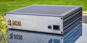
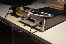
one more picture before I place top cover
the case is around 170x280x55mm, so preaty compact...
no noise, no hummm...
for now
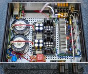
Toroid is 4x18V 1.3A
and 2x6V 1.3A
Anyone used a Khozmo attenuator in this build or elsewhere?
Shunt available in 20k, series in 25k. Which is best for this design?
Link here
In this design we look for about 5K max extra impedance in the source path. Imagine that a 20K series type adds 1/4 worst case source impedance when the wiper divides its nominal value at 1/2.
The voltage on PCB, under load is 17,20V so I hope it will last
That's the proper value. So no worries.
Though I don't remember it having as much as 1V difference between loaded / unloaded. I also don't remember anyone else reporting >18V initial rails with Tea's transistor kits at least. So I got worried if the LEDS VF changed in production lately.
the case is around 170x280x55mm, so preaty compact...
no noise, no hummm...
for now
Toroid is 4x18V 1.3A
and 2x6V 1.3A
Not easy to achieve silence in a DAC & preamp combo so much compact build.

That's the proper value. So no worries.
Though I don't remember it having as much as 1V difference between loaded / unloaded. I also don't remember anyone else reporting >18V initial rails with Tea's transistor kits at least. So I got worried if the LEDS VF changed in production lately.
jea....my memory is little off...
I don't pay much attention as long as everything look's fine...so maybe/probably I remember wrong voltage (18V instead 17V
)..my bad boxed
and, it does produce heat
will se If I could place some small ventilator on low speed...or drill some holes in case
will figure out something
Have you used a thermocouple to measure inside and outside? How many C here and there? You will find a way. A Noctua or alike quality silent fan in low speed maybe. In some bottom holes to back plate spinning air path or a side to side path.
In this design we look for about 5K max extra impedance in the source path. Imagine that a 20K series type adds 1/4 worst case source impedance when the wiper divides its nominal value at 1/2.
So in this case the 25k series attenuator would not be desirable?
My only preference for series or shunt or ladder is they stay within DCG3's technical spec for good bandwidth. To be picked so their output impedance stays around a nominally 20K classic pot's max Zo in circuit i.e. 1/4 its end to end nominal = 5k.
DIYA has old threads in stock for all the classic audio debates of course. I just looked and the series vs shunt pot debate isn't an exception.
Shunt Attenuator Myth
DIYA has old threads in stock for all the classic audio debates of course. I just looked and the series vs shunt pot debate isn't an exception.
Shunt Attenuator Myth
I haven't got anything to measure temperatureHave you used a thermocouple to measure inside and outside? How many C here and there? You will find a way. A Noctua or alike quality silent fan in low speed maybe. In some bottom holes to back plate spinning air path or a side to side path.
used to have some thermometer with scale up to 120* but manage to broke it
so now I'm using Pass heat test which goes like ;
if you can hold you hand for les that 5ces you have like 65*
if you can hold it like 10sec its like 60*
and everything above that you are fine
hope I remember that rule right
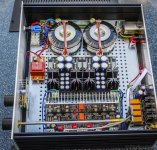
I don't know is it visibile on the pictures but I place some thermal grease betwin L profile and the AL case
the botom of the case gets realy hot, my mobile measure like 50* (have samsung galaxy note 3 with thermal sensor but don't know how acurate it is) but with hand tast I would say it's about right (not more than 55*)...which is just fine for A class
What is the inside box temperature plays the main role for parts reliability. The electrolytic capacitors are all Panasonic 105C rated in your photos for DCSTB and DCG3 at least.
Cheapest half decent DMM that does temperature and comes with a K thermocouple wire sensor is ZT102 whatever branded. About 12 Euro online. Maybe it can replace your broken thermometer.
Cheapest half decent DMM that does temperature and comes with a K thermocouple wire sensor is ZT102 whatever branded. About 12 Euro online. Maybe it can replace your broken thermometer.
Looking for a little insight, When i connect my DCG3 preamp build directly without a pot, I loose a lot of volume /gain. I am currently using a 15v ac x 2, until the Antek become available. The highs also seem muted when compared to when i connect the source directly to the amp. Has any one else had this experience?
- Home
- Source & Line
- Analog Line Level
- Salas DCG3 preamp (line & headphone)