Hi...
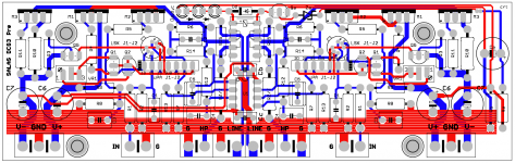
Is it possible (Salas) that a picture of the pcb traces could be posted here ?
I would like to compare my own layout!
Thank you all
Jesper.
Attached
Attachments
Does RZ still need to be 1W if using it as a preamp, or just for headphones?
RZ can be a wire even. Hence RZ/J(umper). Or a 0.1Ω part to just fill the board space nicely. That's the technically correct thing to do. It must be 1W when of substantial value intentionally used for underdamping some dry cans you may want to fluff up. Like some non feedback tube amps do to some small FR speakers. Has no direct effect to the line out route.
Hi again.
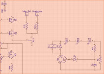
Isen't the relay supposed to make a connection after a short while to lineout, when preamp. is powered on, for avoiding turn on thumb?
Am i right Salas that youre schematic shows an engaged relay ?
Jesper.
Isen't the relay supposed to make a connection after a short while to lineout, when preamp. is powered on, for avoiding turn on thumb?
Am i right Salas that youre schematic shows an engaged relay ?
Jesper.
Attachments
I need a thumb's up (like)- Thank's Salas.
 Its in the smilies --> [More] button on little window next to the advanced answering text window (along with many other comic gestures)
Hi again.
Isen't the relay supposed to make a connection after a short while to lineout, when preamp. is powered on, for avoiding turn on thumb?
Am i right Salas that youre schematic shows an engaged relay ?
Jesper.
Yes my schematic shows it engaged. That will nonetheless happen after some seconds.
I think the quality is very nice on them, and the price compared to some other options is reasonable. In the US, it is hard to beat the price to quality ratio of the Antek parts.
As far as hearing differences between transformers, I dont think my ears are that precise on the matter.
thank you very much for reply
as I remember Peter Daniel also like split bobins 229 trx
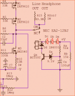
Now that I think about it nobody ever asked me in years of Mezmerize builds why I put a diode across every relay coil like with Dd here. Do you all know why?
Let me take a swag, "The diode eliminates a relay 'transition pop' that would otherwise find it's way into the audio.". How did I do?
Salas,
Have you found any downside to using the uPA68H in place of the unobtanium LSK389 ?
I have been experimenting of late using it in a DOA (Discrete Op Amp) circuit that had been designed for the LSK389, and as far I have have been able to tell it works very well. However I haven't taken any noise measurements that compared the two. Have you?
Good guess at the side effect. The main event is: As the coil's magnetic field instantly collapses when its driving transistor switches off it creates a current pulse that needs a path to the supply unless it will push against the now very high impedance transistor path creating a transient in the hundreds of volts even. That will wear out and eventually kill the transistor. Will also do its best to couple as EMI pulse everywhere near.
I can see some TO-71s lsk389 Stock and Price by Distributor
The uPA is less Yfs more alike the 2SK117 and has great FET to FET in package curves consistency. The LSK389 is not as the K170 exactly. Its faster and has more slant curves. In the preamp there was no noise difference but the IMD was bit better with the uPA. K170 gave very low THD median but it rose up faster than the others towards HF due to its the more capacitive guy in that bunch.
I can see some TO-71s lsk389 Stock and Price by Distributor
Thank you for the lead on the '389s. I just ordered a few from them.
I also ordered some NECs off eBay earlier.
Good guess at the side effect. The main event is: As the coil's magnetic field instantly collapses when its driving transistor switches off it creates a current pulse that needs a path to the supply unless it will push against the now very high impedance transistor path creating a transient in the hundreds of volts even. That will wear out and eventually kill the transistor. Will also do its best to couple as EMI pulse everywhere near.
This is a good explanation Salas
NOT to be offtopic, but i think this is important to know(or interessting)
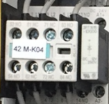
But i was told many many years back, that the purpose of the diode sitting across the coil, not only has the benefit of protecting the electronics, against spikes. The catch is also, that the diode shorts the "self-inductance" which is engaged in the coil, when supply is cut (The coil tries to hold the magnetic field); So actually the diode also gives the relay a faster cutoff sequence, preventing sparks on the contactor too. So diode also protect the relay...
I also see this everyday in the industri.
I have attached a picture of a diode sitting across a coil in one of our cranes here at Port of Fredericia
Just my 2cent's.
Jesper.
Attachments
Hi
Se post #47 also :
Jesper.
Se post #47 also :
Because no capacitors are in the signal path a relay system timed to 5 sec delay by Ra Ca lets no settling bump during power on to get out. It also disengages quickly during power off. Dc Db Da LEDS drop the rail voltage to 12V relay safe working range territory. And you know its on. One of them can be actually brought to the front panel as "ready" sign because they light up only when the relay clicks.
Jesper.
- Home
- Source & Line
- Analog Line Level
- Salas DCG3 preamp (line & headphone)