Salas I am still struggling with finding a perfect case for my needs. If for example I decide to separate psu, should I move transformers into other box, make smal CRC there just so I don't run AC and connect it right after rectifiers in the psu boards? Or there are some cons i don't see in doing so?
Salas, I am having a hum/mostly buzz problem in my balanced build.
With pin1's of the input and output XLR of each channel and one end of a CL60 connected at the same point on the chassis, I connected the other end of the CL60 to the G point on the DCG3 next to Line out. I got a buzz. Then I removed this end from the DCG3 and connected it to the G point of the DCSTB. Still buzz but a bit less. Finally I removed the end from the DCSTB G and let it float, so essentially no CL60 connection and its very quiet. Must mention that R7's are lifted from ground and linked together.
What do you advice?
Thanks. nash
Looks good. Time to put the servo op-amp in now.
Salas, yes, I do think so as well. Servo in, a few connectors and give it a fist listen
") Looking forward to connecting it to my dac and headphone.
Looking forward to connecting it to my dac and headphone.Later then think about a proper housing. For me, this is always the most challanging part.
Cheers Ernst
Later then think about a proper housing. For me, this is always the most challanging part.
Cheers Ernst
I hear you!
Salas, I am having a hum/mostly buzz problem in my balanced build.
With pin1's of the input and output XLR of each channel and one end of a CL60 connected at the same point on the chassis, I connected the other end of the CL60 to the G point on the DCG3 next to Line out. I got a buzz. Then I removed this end from the DCG3 and connected it to the G point of the DCSTB. Still buzz but a bit less. Finally I removed the end from the DCSTB G and let it float, so essentially no CL60 connection and its very quiet. Must mention that R7's are lifted from ground and linked together.
What do you advice?
Thanks. nash
Unfortunately I don't have a balanced build to experiment along with you and give you solid practical advice. There is only Kostas's (MagicBus) build example that isn't using linked R7s or CL60. I could attempt to theoretically analyze your config but in real builds there are loop area and rest of system grounding factors at play also. I would just say use the most quiet config you can practically achieve and don't forget to check the outputs DC offset also on the bench for all possible signal modes.
My SLBs measure 10 ohm DCR. What does CL60? Also, did you test to connect circuit GND directly to chassis?Salas, I am having a hum/mostly buzz problem in my balanced build.
With pin1's of the input and output XLR of each channel and one end of a CL60 connected at the same point on the chassis, I connected the other end of the CL60 to the G point on the DCG3 next to Line out. I got a buzz. Then I removed this end from the DCG3 and connected it to the G point of the DCSTB. Still buzz but a bit less. Finally I removed the end from the DCSTB G and let it float, so essentially no CL60 connection and its very quiet. Must mention that R7's are lifted from ground and linked together.
What do you advice?
Thanks. nash
Last edited:
Maybe just a capacitor instead of Thermistor will work for him. Also pin1 "philosophy" can be opinionated:
http://www.diyaudio.com/forums/pass-labs/117444-xlr-pin-1-question-chassis-vs-circuit-ground.html
http://www.diyaudio.com/forums/pass-labs/117444-xlr-pin-1-question-chassis-vs-circuit-ground.html
If one designs from scratch a complete audio system, then AES standard is the way to go. But when we have to connect devices that do not confirm with AES then only way is to follow the grounding scheme of each device. Also, AES standard, i.e. pin 1 to chassis, does not allow parallel XLRs and RCAs. The pin 1 problem occurs when the shield connected to it forms a returning path for signal current. Possible solutions to this could be the following;
1) Pin 1 of both devices to each chassis.
2) Pin 1 of first device to circuit GND and pin 1 of the second to chassis.
3)#2 reversed
What I do;
Dac chip pin 1 connected to circuit GND and chassis - I can't do anything about that.
DCG3 pin 1 is at the moment connected to chassis and RCA for SE function to circuit GND but I think pin 1 should also go to circuit GND and that's what I'm going to do.* Amps pin 1 to chassis
* I see DCG3 as a replacement for the sound card analogue section; balanced signal from the DAC chip amplified by what it took the place of the opamps > balanced line out.
My SLBs measure 10 ohm DCR. What does CL60? Also, did you test to connect circuit GND directly to chassis?
Around 10R. I have not connected circuit G to chassis yet.
I shall experiment and report back. I have a couple of options to explore. Anyway the amp is very quiet without a SLB but I would like to incorporate it from the safety issue.
BTW Pass amps do not have pin1 directly to chassis. I have confirmed this on a XA100.8; there is around 10R between pin 1 and the chassis perhaps because it has the option of also using RCA so pin1 is most likely to PCB.
Thanks Salas and Kostas.
nash
.
Hey....
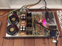
For what is worth i did this in my build :
-But not balanced build through!
Mains earth (yellow/green) are connected to chassis directly.
The metalchassis of the pot. -is the only place where signalground is connected to chassis.
The signalground are not connected to chassis anywhere else, but i did make holes for that if needed. - But one connection is better than many i think.
Jesper.
Hey....
For what is worth i did this in my build :
-But not balanced build through!
Mains earth (yellow/green) are connected to chassis directly.
The metalchassis of the pot. -is the only place where signalground is connected to chassis.
The signalground are not connected to chassis anywhere else, but i did make holes for that if needed. - But one connection is better than many i think.
Jesper.
So you are not using any connection or SLB from power supply or DCG3 to chassis?
nash
So you are not using any connection or SLB from power supply or DCG3 to chassis?
nash
If you look at the picture, you see that there is a wire from potmeterchassis to the chassis. And yes, it's the only spot where signalgnd / gnd is connected.
Jesper.
Attachments
RCA/Phono do not have a pin1. There are only two wires and both are signal wires. Neither connect to chassisIf one designs from scratch a complete audio system, then AES standard is the way to go. But when we have to connect devices that do not confirm with AES then only way is to follow the grounding scheme of each device. Also, AES standard, i.e. pin 1 to chassis, does not allow parallel XLRs and RCAs. The pin 1 problem occurs when the shield connected to it forms a returning path for signal current. Possible solutions to this could be the following;
1) Pin 1 of both devices to each chassis.
2) Pin 1 of first device to circuit GND and pin 1 of the second to chassis.
3)#2 reversed
What I do;
Dac chip pin 1 connected to circuit GND and chassis - I can't do anything about that.
DCG3 pin 1 is at the moment connected to chassis and RCA for SE function to circuit GND but I think pin 1 should also go to circuit GND and that's what I'm going to do.* Amps pin 1 to chassis
* I see DCG3 as a replacement for the sound card analogue section; balanced signal from the DAC chip amplified by what it took the place of the opamps > balanced line out.
A 3pole TRS, or XLR, have two signal pins, neither connect to chassis.
Pin 1, the screen connection, connects to chassis.
The screen around the two signal wires does not go to audio. this screen carries interference and is taken direct to chassis.
Test your equipment using John Windt's Hummer. And sort each piece that has a Pin1 problem. or throw the errant equipment in the bin.
Hypex and Bonsai have published info on wiring Pin1
Attachments
Last edited:
In real life pin 1 should be connected where the interconect's shield will not circulate any current. This depends on the actuall implementation....
BTW Pass amps do not have pin1 directly to chassis. I have confirmed this on a XA100.8; there is around 10R between pin 1 and the chassis perhaps because it has the option of also using RCA so pin1 is most likely to PCB.
Thanks Salas and Kostas.
nash
.
Yes, I wouldn't insert SLB between circuit GND and chassis if I could. But since I use an audio PC the only other way to avoid ground loop noise would be isolation transformer and I don't like this solution. Anyway, for balanced connection SLBs could stay out. They are necessary only for SE connectionHey....
For what is worth i did this in my build :
-But not balanced build through!
Mains earth (yellow/green) are connected to chassis directly.
The metalchassis of the pot. -is the only place where signalground is connected to chassis.
The signalground are not connected to chassis anywhere else, but i did make holes for that if needed. - But one connection is better than many i think.
Jesper.
RCA/Phono do not have a pin1. There are only two wires and both are signal wires. Neither connect to chassis
A 3pole TRS, or XLR, have two signal pins, neither connect to chassis.
Pin 1, the screen connection, connects to chassis.
The screen around the two signal wires does not go to audio. this screen carries interference and is taken direct to chassis.
Test your equipment using John Windt'sHummer. And sort each piece that has a pin1 problem. or throw the errant equipment in the bin.
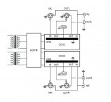
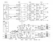
You are right, but I think I'm also right. It sould be clarified that we are trying to find what to do with pin 1 in a preamp that it's not differential. It's just two SE preamps that will amplify what they will take in the inputs. In this case each SE preamp will take one phase of a balanced signal. That would ask for coaxial cables and RCAs. XLRs are inserted for compartibility with other balanced devices. I attach two schematics, one is the wiring of "my" DCG3 and the other is my differential preamp where pin 1 can be done properly.
The test may be usefull though. Thanks!
Attachments
you are showing a common ground for all the different returns and chassis and everything that might loosely be called "ground".
You need to disconnect the the Signal Returns from the chassis. Each Signal Return should be close coupled with it's Signal Flow all the way from source to receiver. Do not take the return on a separated route to some remote star. That invites interference contamination.
You need to disconnect the the Signal Returns from the chassis. Each Signal Return should be close coupled with it's Signal Flow all the way from source to receiver. Do not take the return on a separated route to some remote star. That invites interference contamination.
So you are not using any connection or SLB from power supply or DCG3 to chassis?
nash
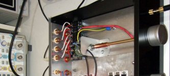
I also use no SLB in my DCG3. The only one SLB of the whole system is located in the power amplifier. My DCG3 chassis has a bolted wire connected to mains earth. The signal ground is again bolted to chassis with a thick wire taken from one point only where the In-Select returns line and the channels input coax screens meet at the volume pot's return points bridged. Pot's metal parts are already at chassis potential because mechanically secured with an L bracket. DAC, preamp, power amp, are all using three wire IEC. No ground loops buzz in the background with ear on the HF horn's mouth.
Attachments
- Home
- Source & Line
- Analog Line Level
- Salas DCG3 preamp (line & headphone)