Its not an H3 preamp when normally set, its like in post#1
Are your C1 10pF & your C2 33pF verified? Does the H profile change if you tweak VR1? Maybe you could make R1 4.7k
C1 is high quality C0G/NP0 ceramic from Digikey - but I never actually measured it. C2 is high quality silver mica cap from Digikey as well.
C1 says 10J and C3 says 33 and +/-5%
I never measured Idss of cans used. I have 2 more from same batch I can measure. Will try grounding cans. I measured resistance on pot between wiper and input at point where a louder setting would cause oscillation - 13kohm. Could we make R2 100k and C1 bigger 30pF or 45pF?
I never measured Idss of cans used. I have 2 more from same batch I can measure. Will try grounding cans. I measured resistance on pot between wiper and input at point where a louder setting would cause oscillation - 13kohm. Could we make R2 100k and C1 bigger 30pF or 45pF?
Last edited:
C1 says 10J and C3 says 33 and +/-5%
I never measured Idss of cans used. I have 2 more from same batch I can measure. Will try grounding cans. I measured resistance on pot between wiper and input at point where a louder setting would cause oscillation - 13kohm. Could we make R2 100k and C1 bigger 30pF or 45pF?
You haven't done anything really wrong, it looks like its the cans that are more difficult to work with, especially when not housed in a metal box with coax runs, the standard PSUs, etc. You should gradually up R1 and see about the point of stability, also about grounding the cans for now. You can play with VR1 while you are FFTing to see about affecting the harmonic profile also. The second looks low where it should be, maybe that third and seventh are instability or interference related. No fifth which is kinda weird when there is a seventh. If you got some 2SK170s or 117s you could also try them in the uPAs places meanwhile and remove the cans if not taming enough with those tials. Ask Tea for a couple of uPAs to have for comparisons anyway.
Nothing fancy, ffset 0 - 1mv without servo.
Yes it can be low on its own but don't let it fool you into skipping the op-amp because thermals are gonna crawl in at a point and they should be safeguarded. Congrats for the handmade stuff.
Nothing fancy, ffset 0 - 1mv without servo.
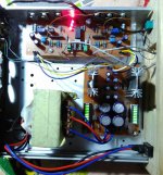
Nice build Didiet78
")
Did you try listning to it yet?
(Btw. Didiet i am assambly second channel of our mimiAlaphJ theese day's)
Jesper.
Nice build Didiet78
Did you try listning to it yet?
(Btw. Didiet i am assambly second channel of our mimiAlaphJ theese day's)
Jesper.
Not yet, just powr on and offset trimming.
(i will ask in mimi thread
)You haven't done anything really wrong, it looks like its the cans that are more difficult to work with, especially when not housed in a metal box with coax runs, the standard PSUs, etc. You should gradually up R1 and see about the point of stability, also about grounding the cans for now. You can play with VR1 while you are FFTing to see about affecting the harmonic profile also. The second looks low where it should be, maybe that third and seventh are instability or interference related. No fifth which is kinda weird when there is a seventh. If you got some 2SK170s or 117s you could also try them in the uPAs places meanwhile and remove the cans if not taming enough with those tials. Ask Tea for a couple of uPAs to have for comparisons anyway.
I tried tweaking the VR1 while looking at FFT, no change really and after removing the opamp saw that I had changed DC offset to as much as 260mV.
I went big and added a 15k vs 3.3k for R1 to see what would happen and this changed the harmonic profile to higher and descending from H2 with lots of components. The amp still oscillates when the volume pot is turned up more than about halfway on a 50k pot. I would have thought adding the 15k would have fixed this. So I can probably adjust R1 to get the correct harmonic profile.
I added a ground wire (soldered onto SK389 tin can tab) to the input JFET housing. This doesn't solve the blowing up problem.
Here is current FFT with JFET ground strap and 15k input R1:
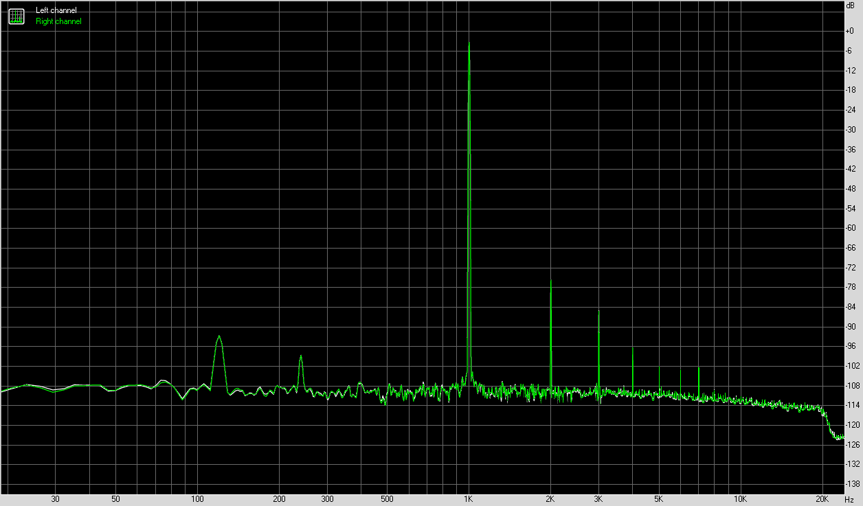
Maybe R1 at 4.7k will fix the harmonic profile, but I still have an amp that oscillates wen volume is turned up. This is not due to clipping - the VU meter shows -3.4dB still to go.
Maybe IRF9610 gate stoppers need to be increased from 33R to say 100R or 220R?
As I am listening to a song and as I adjust the pot beyond where the FFT told me it should be oscillating, I do not hear any sudden change in sound quality. I wonder if this has something to do with an oscillation in the measurement DAC.
Attachments

Last edited:
It takes a scope to know its oscillating for sure or with what associated components. I can't be making out if its a mini lab quirk or not. I would exchange for uPAs first to have some reference.
During those times you tweaked something and saw much different FFTs, any changes in the listening should have been felt tonally somehow or up to pretty dramatic, especially where the oscillation fireworks break out.
P.S. Higher value IRF gate stoppers are against phase margin in general for this one but without scoping spots its shooting in the dark anyway.
Very strange is that I don't really detect anything different in the listening when the FFT supposedly goes berserk. It may just be a quirk of the UCA202. My Focusrite interface card should be coming soon, so maybe see if things improve then.
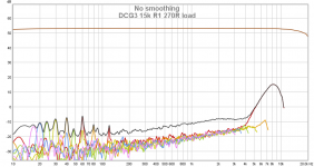
I was curious and tried using REW (speaker meas software) and looked at HD plots with volume pot in "good position" vs "bad position" and the HD plots don't look too different. There is a problem with rising 2nd harmonic peak though in the higher frequencies.
I was curious and tried using REW (speaker meas software) and looked at HD plots with volume pot in "good position" vs "bad position" and the HD plots don't look too different. There is a problem with rising 2nd harmonic peak though in the higher frequencies.
Attachments
Yes, I have 2sk170's I can try but you would think matched monolithic sk389's would be the cat's meow here. The little solder pads for the metal can are very small and I would prefer not to have to remove that little metal can package for fear of damaging the pads. Although Teabag PCBs have extra thick copper so may be fine.
As for ever removing the LSKs better cut them at board level, they got plenty of lead length to remain usable. You can go clean the little pads with a manual de-soldering pump on one side and the iron on the other whenever, later. Because the plastic alternatives all go to the uPA pads. They have drain gate source marked for each side JFET's pins already.
- Home
- Source & Line
- Analog Line Level
- Salas DCG3 preamp (line & headphone)