Lets see how a standard DCG3 (100mA output stage bias NEC uPA68H J1,J2 BC327-40 Q1,Q2 DCSTB PSU) behaves for THD vs Frequency sweep at unity volume position, line out, 20kΩ load.
THD rise to the treble is a low smooth trend by second harmonic. Multi-tone resolution equivalent to 18 bits digital. No IMD haze between the tones. Absence of odd harmonics in the 1kHz 1V RMS sine test. Overall not bad for an eight transistors two stage circuit.


THD rise to the treble is a low smooth trend by second harmonic. Multi-tone resolution equivalent to 18 bits digital. No IMD haze between the tones. Absence of odd harmonics in the 1kHz 1V RMS sine test. Overall not bad for an eight transistors two stage circuit.
I put pins for J1-J2 to present easy THD comparisons across the spectrum between some JFET types. The higher Yfs ones have some advantage below 500Hz but their higher capacitance makes them worse in the HF. Also the 2nd (red) and 3rd (orange) harmonics walk differently in each case. uPA68H is excellent & very consistent. Close performance with the 2SK117. Not surprisingly because of alike Yfs Ciss Crss. 2SK170 nice and does as mentioned for higher Yfs. An exaggerated example of this is the very high Yfs 2SK369. A surface mounted BF862 experiment was 10-15dB inferior to the rest. I suspect oscillation due to its RF classification. Maybe needs an smd μH inductor at its gate pin. And/or direct mounting to specially designed main pcb with ground guards etc. Proved impractical for just dropping it in the dcg3 to perform at least as well as the others anyway.

")


I’ve recently upgraded my distortion measurement equipment with Cosmos ADC, Cosmos APU and Victor’s signal generator. This provides reliable measurements below -140 dBc levels, with threshold at -150 dBc. Took the opportunity to measure again DCG3 distortion at 0.5 Vrms output, which is enough for most amplifiers to have from 1 W to 4W at output. Both uPA68H and 2SK170BL provide H3 20 dB below H2, and H2 has perfect negative phase (for those who think this is important). All high order harmonics after H3 may be mostly equipment distortion artefacts.
Great results.
Great results.
Attachments
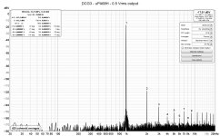
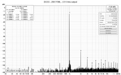
Very benign harmonic behavior. And that's in the first watts producing signal level where the audible resolution is. The noise floor is resolved very low with your new measurement gear. Great. *Why -17.6dBV at top right when 0.5VRMS is -6dBV? Uncalibrated? Maybe also use dBc which sticks to zero.
In this case dBV level is referenced to nominal Cosmos ADC input level of 1.8 V. Another reason is that Cosmos APU (active notch filter in front of ADC) has nominal output at -6dB from input (not related to notch attenuation which is compensated). So, we have 0.5 Vrms which is at -11.3 dB relative to nominal 1.8 V, and notch brings that to -17.3 dB. Precise enough.


I used the SalasSSLV1.1 supplies. The difference is not night and day but the more I listen the more I like the DCG3 with the UBIBS.Marra,
What PSU did you have earlier in your DCG3 build?
Thank you all for your response. The kit is already on its way to me.
I have the following question.
Is there an optimal operating temperature for the output transistors?
I plan to reuse a power amplifier chassis with large side heat sinks, and I'm worried whether such a heat sink will be too large and the transistors will never reach their optimum operating temperature.
- Home
- Source & Line
- Analog Line Level
- Salas DCG3 preamp (line & headphone)