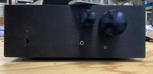
Yesterday, I took all my courage and finally put all the parts together (into its chassis).
There's still a lot of little and not so little things I am not satisfied with or really being flawed, but it seems it is all mechanical stuff. If only, dear Salas, I'd have listened to you and had placed the DCG-board vertically (either on the side or mounted on a heatsink of sorts), this would have spared me the hassle of fighting for most every millimeter in the chassis' depth. I'm contemplating a layout-update to do this...
The other bug really asking for a remedy is the volume-pot's shaft being just that liiittle too short. The knob can't be properly mounted, it is about something like 2 mm. Argh.
Now, to the channels's offsets (Inputs shorted):
Channel 1 is a bit nervous and jumps between -+1mV DC
Channel 2 (
I think it's time to lend it a first ear, what do you think?
There's still a lot of little and not so little things I am not satisfied with or really being flawed, but it seems it is all mechanical stuff. If only, dear Salas, I'd have listened to you and had placed the DCG-board vertically (either on the side or mounted on a heatsink of sorts), this would have spared me the hassle of fighting for most every millimeter in the chassis' depth. I'm contemplating a layout-update to do this...
The other bug really asking for a remedy is the volume-pot's shaft being just that liiittle too short. The knob can't be properly mounted, it is about something like 2 mm. Argh.
Now, to the channels's offsets (Inputs shorted):
Channel 1 is a bit nervous and jumps between -+1mV DC
Channel 2 (
) is similarly jumpy: +- 1mV DCthe always been good channel
I think it's time to lend it a first ear, what do you think?
That is good progress!Yesterday, I took all my courage and finally put all the parts together (into its chassis).
There's still a lot of little and not so little things I am not satisfied with or really being flawed, but it seems it is all mechanical stuff. If only, dear Salas, I'd have listened to you and had placed the DCG-board vertically (either on the side or mounted on a heatsink of sorts), this would have spared me the hassle of fighting for most every millimeter in the chassis' depth. I'm contemplating a layout-update to do this...
The other bug really asking for a remedy is the volume-pot's shaft being just that liiittle too short. The knob can't be properly mounted, it is about something like 2 mm. Argh.
Now, to the channels's offsets (Inputs shorted):
Channel 1 is a bit nervous and jumps between -+1mV DC
Channel 2 (
) is similarly jumpy: +- 1mV DC
I think it's time to lend it a first ear, what do you think?
Per the building guide the offset values appear to be within limits.
As for the rod a (second) shaft coupler or otherwise a new rod will solve this issue, but I guess you have thought about this already.
These moments I also try to remind myself of the proverb "Perfection is the enemy of the good!".
Yes indeed (to both "perfection" and "shaft coupler") ") .
.
The problem is that I can't easily add a coupler as there's no space for it—I'd have to make any extension sit flush on the shaft's head. As it is a knurled, "slitted" shaft, I can use the slit and insert a little piece of aluminum/brass.
Or open up the knob's hole (make space for a plugged-over tubular extension)—probably the easiest way?
Or file down 2 mm on the knob's underside
Or make the knobs recessed (requires a workshop and €)
.The problem is that I can't easily add a coupler as there's no space for it—I'd have to make any extension sit flush on the shaft's head. As it is a knurled, "slitted" shaft, I can use the slit and insert a little piece of aluminum/brass.
Or open up the knob's hole (make space for a plugged-over tubular extension)—probably the easiest way?
Or file down 2 mm on the knob's underside
Or make the knobs recessed (requires a workshop and €)
Not sure I understand, do you mean the pots shaft is too short to go through faceplate, which I assume is the 10mm thick one, or no?Yes indeed (to both "perfection" and "shaft coupler")
The problem is that I can't easily add a coupler as there's no space for it—I'd have to make any extension sit flush on the shaft's head. As it is a knurled, "slitted" shaft, I can use the slit and insert a little piece of aluminum/brass.
Or open up the knob's hole (make space for a plugged-over tubular extension)—probably the easiest way?
Or file down 2 mm on the knob's underside
Or make the knobs recessed (requires a workshop and €)
If yes, I solved the problem with a shaft extension kit from Partsconnexion, about 20 bucks. They give the length of the bearing as 10mm, but it is long enough to go through and get the nut tightened on other side on the 10mm chassis faceplate.
Russellc
JB weld maybe?Blu tack probably will be too soft or maybe a fast hardening resin to fill the gap?
You got me right, and not quite right
Yes, the shaft is too short. I mounted the pot onto an aluminium-plate, and this plate onto the front's back, the shaft going through the 10mm faceplate, and now the available length that is left is ~5 mm (I unfortunately only got a pot with a 15 mm shaft!)
I can't move the pot backwards (to put a shaft-extension inbetween), either, because space is scarce and everything is just snugly (or even a bit overstuffed) in its place.
I went the easyer route and widened the knob's hole, thus I can plop an extension directly onto the shaft and ZANG it is done (after finetuning this for a tight fit.
You will see some of it rather soon!

david
Yes, the shaft is too short. I mounted the pot onto an aluminium-plate, and this plate onto the front's back, the shaft going through the 10mm faceplate, and now the available length that is left is ~5 mm (I unfortunately only got a pot with a 15 mm shaft!)
I can't move the pot backwards (to put a shaft-extension inbetween), either, because space is scarce and everything is just snugly (or even a bit overstuffed) in its place.
I went the easyer route and widened the knob's hole, thus I can plop an extension directly onto the shaft and ZANG it is done (after finetuning this for a tight fit.
You will see some of it rather soon!
david
Salas, what can I say?
Your pre amp design is (a)live and in combination with the First Watt F6 it is a very good match that does not lack power or dynamics: I am very happy with the result!
I have no words to express my gratitude for sharing this with us, for answering my questions and for all the troubleshooting.
Tea-Bag, thanks very much for lifting this off the ground: your excellent kits make it easy for us!
Shout out to community members Tea-Bag, pfarrell, Marra and myleftear for a lot of practical advise and thought exchange.
Simon
To avoid further thread-clutter, I just opened my "myleftear builds Salas' DCG3"-thread, where I will add whatever is to come, that I feel like wanting to make public and doesn't really belong here as it is not straightly cencerning DCG3... (that shaft-thing as a first subtopic)
Please feel free to post whatever comment around my build in there...
Please feel free to post whatever comment around my build in there...
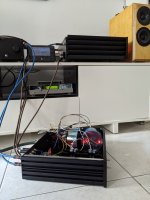
Still a bit of a test bench situation, but I could not wait any longer.You are welcome. System picture awaited.
Attachments
I thought I had it...
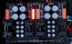
After my first layout with a quite fat heatsink and the board mounted horizontally, the build was, well, overstuffed. Not that it's airy as it is becoming right now, but still way better than before.
But of course a new issue occurred: The volume-relay is not working anymore.
On for a third round. 🎢
(It seems like this is my karma: The things I make aren't good before the third time!)
@pfarrell don't wan't to make you wait any longer to see something, so here's a glimpse of what will be my DCG3 ( it is the one with the "always been good channel" <- I just love that)
After my first layout with a quite fat heatsink and the board mounted horizontally, the build was, well, overstuffed. Not that it's airy as it is becoming right now, but still way better than before.
But of course a new issue occurred: The volume-relay is not working anymore.
On for a third round. 🎢
(It seems like this is my karma: The things I make aren't good before the third time!)
@pfarrell don't wan't to make you wait any longer to see something, so here's a glimpse of what will be my DCG3 ( it is the one with the "always been good channel"
<- I just love that)Attachments
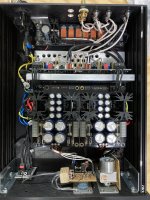
Am I really to be called "Mr. Bungle"?
It seems so:
Transformer output is good, 18.6VAV + 18.6VAC
After de- and reconnecting the DCSRB, I first measured a weird number, like +34 / -17 VDC (or something like that)
Then I accidentally shorted the V+ (spark, fuse blown)
replaced fuse, turned on: V+'s LED-bank comes up immediately and much brighter than the 3 others.
It now measures +42VDC / +24VDC. (black probe on GND both times)
I conclude that I've blown something up? (there was no smoke ar anything but that spark)
The other channel measures good. This other channel feeds I-select, which turns on and outputs 12.1VDC.
LEDs (Channel indicators) are lit.
Relay (fed by I-select) not responsive but haven't checked connections. It was good before disassembly.
When I fed the relay, which feeds the Pot-motor, it first didn't do anything, with twisted wires didn't stop running.
All this stuff is disconnected for now, want to check connections first, then see how to proceed.
Attachments
Last edited:
that's the answer I was afraid to get...
Makes me feel sorry.
I was obviously overconfident—everything was working, and everything was marked (like, this wire there and that wire here...), and boof.
It seems the J2 PF5102 are becoming hard to get. Does somebody know of a good reliable source? Or, would tea-bag send me replacements? (After I was able to confirm it's blown at all)
I should also add that fuses are generally intended to "stop the fire". That no magic smoke was released means the fuse did its job. True current limit circuits are intended to allow equipment to shut down gracefully from an overload and recover when the fault is removed. In this sense, a fuse is not a current limit circuit. The response time of a fuse is too long to reliably save components.
- Home
- Source & Line
- Analog Line Level
- Salas DCG3 preamp (line & headphone)