I remember having these questions previously, but stumped again. I am down to 6 capacitors left and I have 6 capacitor holes, so good so far.
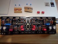
What I have left is 2 small red caps that say.15, and two sets of two small blue caps. One has a red line on it, one has a black line on it. I put the small red ones under the board in the positions above and below the 8 legger plug on my first build, assuming that is correct, Cb and Cc? I can't remember which of the small blue caps, "Red line" and "black line" goes in which position, C1 or C2?
Also, question about R3. Seems like I recall that coming up before as well. BOM calls for 150 ohm, I have 220 ohm left. I am assuming this is either a substitution, or I have put one in wrong position?
Also, the three LEDs. short leg in round or square hole here?
Thanks,
Russellc
Attachments
Let's see how well I do before someone who knows comes along.
First question, no idea. I remember reading or being told last time the color of the mark determined position? Lost on that one
The resistor, 220 ohm I'm calling good, there are not other 150 ohm I misplaced.
Leds, I have had builds that reversed the usual "round hole square hole" thing so want to be sure here. These boards, and most of the others Tea has been in on are very high quality and thicker than the usual run of the mill boards, or even some high quality examples. Un soldering requires much skill and extreme patience, so avoid mistake before I make it is good. Previously in other builds seems I remember a rule about pointing towards positive, reviewing the schematic may help me, let's see.
Guess I only "answered" one. Likely mixed up on that!
Russellc
The two red 0.15uF are surely Cc Cb rail decoupling caps for the Op-Amp. The blue ones are C1 C2 filter & stability C0G zero thermal drift caps 10pF & 33pF. Very important not to mix up their places. If you can't measure them PM Tea to inform you which marker color tells which is which. They must be having some tell tale fine print on their bodies though. Try to read with a torch and a magnifying glass.
LEDS you can try with DMM's diode mode. Many meters give out enough voltage to try LEDS but some don't. In any case if they light up on diode test they do it when the DMM's black probe is at their cathode. So you confirm their cathode and anode legs.
R3 220R is what's recommended when J3 has more Idss than my prototype with 150R R3. Surely handpicked to match particular batch J3 so its ok to use.

Just found where that info was....it was in the blog. I've been rereading the main thread, and finally I saw the post where there was the group by, thought it might have been there, from there saw a link to the blog I had forgotten about!
R3 is 221R in this kit.
The red represents 10pf, the black 33pf
There is also a note on led orientation but the link doesnt work. At least I figured out where the info came from I remembered!
Russellc
R3 is 221R in this kit.
The red represents 10pf, the black 33pf
There is also a note on led orientation but the link doesnt work. At least I figured out where the info came from I remembered!
Russellc
yup. you are right, shorter leg has larger part....Shorter lead should be negative i.e. cathode and connected to the fatter element inside
Just check the voltage spec on diode test of any prospective buy. Fluke 17B+ says 2V for instance. That would light up even a green LED. But not a blue or a white.
You can never have too many multimeters. On the other hand why not get a cheap component tester instead
Ah, indecision. My 327-40 parts have numbers on them 520, 521, 522 and 523. Do these numbers have measurement relevance?
If so, are these so close it matters not where they go, or should certain numbers be grouped together? 520 and 522 then 521 and 523?
My feeling is it makes no difference, but these boards are best soldered correctly the first time.
If so, are these so close it matters not where they go, or should certain numbers be grouped together? 520 and 522 then 521 and 523?
My feeling is it makes no difference, but these boards are best soldered correctly the first time.
I will say this things ability to resolve detail is astonishing.Russellc, glad you have everything working. I am interested to know how the DCG3 differs in sound from the Iron Pre. I've never heard that one.
I think you will like the USFPS (or whatever it's called). A buddy borrowed mine and liked it better than both his CH Precision and CAT stages.
Russellc
- Home
- Source & Line
- Analog Line Level
- Salas DCG3 preamp (line & headphone)