")
Some new headphone cushions came this afternoon. The originals were open-cell foam and these are closed. I like how they feel, but it drastically alters the frequency balance.
I was expecting the output devices to run hot without a proper heatsink. But the dissipation seems quite good and the transistors are just warm to the touch. I am running the output bias at about 135mA.
Someone on the local audio club mailing list posted some awful IRF9610 curves he measured and suggested I try FQP3P20s instead. I was curious if you have experimented with different types of output devices, and if you've ever seen bad behavior from the IRF9610s.
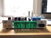
Here's another picture for you. I love the open-chassis look, even though it's totally impractical. I screwed up and reversed the + and - op-amp terminals on the AD823 footprint, so had to do board surgery. Otherwise, everything has gone smoothly.
I was expecting the output devices to run hot without a proper heatsink. But the dissipation seems quite good and the transistors are just warm to the touch. I am running the output bias at about 135mA.
Someone on the local audio club mailing list posted some awful IRF9610 curves he measured and suggested I try FQP3P20s instead. I was curious if you have experimented with different types of output devices, and if you've ever seen bad behavior from the IRF9610s.
Here's another picture for you. I love the open-chassis look, even though it's totally impractical. I screwed up and reversed the + and - op-amp terminals on the AD823 footprint, so had to do board surgery. Otherwise, everything has gone smoothly.
Attachments

Yes I had experimented. A good portion of development time was about active parts selection. Since its a very simple signal path architecture that must be working with specific parts in careful synergy. For output I had started with those FQP you mentioned. Because I knew about the infamous IRF PMOS gm kink etc. But THD was eventually measuring significantly better with the IRF9610s in this application. Probably due to better driven by the input stage along with output stage style and bias level indifference but the end result circuit total was superior when with them in the equation. Mine are Vishay to be specific.
Cushion types are integral to headphones FR no doubt. Nice sunlight rays through green FR4 perspective photo.
Cushion types are integral to headphones FR no doubt. Nice sunlight rays through green FR4 perspective photo.
Probably due to better driven by the input stage along with output stage style and bias level indifference but the end result circuit total was superior when with them in the equation. Mine are Vishay to be specific.
Cushion types are integral to headphones FR no doubt. Nice sunlight rays through green FR4 perspective photo.
Thanks for the information. I have Vishay parts here too. Since International Rectifier is no more, do you have any idea who picked up their semiconductor manufacturing? Or do you suppose the "bad" parts are no longer in production? Either way, I'm not going to worry about it.
I'm enjoying my DCG3 with the PX-100s. I'm thinking seriously about buying some real headphones, but I think I'll stick with these for now and see if I'm still interested in the concept once the novelty starts to wear off.
I'm also starting to work on a mk. 2 version to package in a proper chassis...
-Henry
IR power products line was acquired by Vishay fourteen years ago. Mosfets have the Siliconix logo. A fat S with an i inside stamped on their bottom left. In which fabs with what newer process or not they make them I have no idea. They must be owning numerous fabs and/or making production partnerships globally. Siliconix belongs to Vishay. Eventually IR as a whole got sold and embodied to Infineon five years ago.
About new larger headphones have a look in the HiFiMan Sundara also.
About new larger headphones have a look in the HiFiMan Sundara also.
Is there any reason to not use Multicomp Transformers? There's good discounts periodically.
https://canada.newark.com/multicomp/mcta050-18/toroidal-transformer/dp/38K4883
https://canada.newark.com/multicomp/mcta050-18/toroidal-transformer/dp/38K4883
Last edited:
Is there any reason to not use Multicomp Transformers? There's good discounts periodically.
https://canada.newark.com/multicomp/mcta050-18/toroidal-transformer/dp/38K4883
There seems to be a miss-print. It is either a 15 VA transformer or the secondary mA is way off.
A 50 VA transformer in that voltage (2x18) would be 1390 mA in each winding.
Here is an Antek 50 VA 2x18V 1.4 Amp for $17.50 all the time:
AS-0518 - 50VA 18V Transformer - AnTek Products Corp
Rush
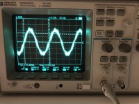
Interesting, I get really bad results when I use the DCG3 as a preamp in the main system. Works fine if I plug the headphones in at the same time, though. I figured oscillation, and sure enough. Right channel only, though.
I'm going to dig into it now, but I wonder if you've had any issues with stability in this circuit.
-Henry
I'm going to dig into it now, but I wonder if you've had any issues with stability in this circuit.
-Henry
Attachments
No oscillation issues with the original layout and values. See if you need a higher value Rout damper (R15) for the specific build and interconnecting leads. Or a higher Rin (R1). Its value and distance to input JFETs gates can be critical. Especially with higher transconductance parts like the K170 and related.
Interesting. The other channel is fine. I haven't found anything obviously wrong yet. It's a stubborn oscillation, doesn't want to change frequency or amplitude if I poke my fingers on the back of the board. I have to think about it some more, will keep you up to date.
-Henry
-Henry
There seems to be a miss-print. It is either a 15 VA transformer or the secondary mA is way off.
A 50 VA transformer in that voltage (2x18) would be 1390 mA in each winding.
Here is an Antek 50 VA 2x18V 1.4 Amp for $17.50 all the time:
AS-0518 - 50VA 18V Transformer - AnTek Products Corp
Rush
I'm positive its 50VA so, misprint I guess.
The Antek will cost 2-3 times in Canadian Funds but they look nice so might consider them. Thanks!
Also check if the servo chip induces that by one side. You had to rewire something around it in your test board I recall. Maybe not locally decoupled well (?)
Thanks for the suggestions. All the parts values look good, board layout looks good. Bias currents look good. The gain is right and the circuit plays music, so everything is roughly correct.
I found that hanging a test lead on the gate of J2 and moving it around could either increase or entirely eliminate the oscillation. I cut a piece of cardboard, wrapped it in aluminum foil, and insulated it with masking tape. I taped it to the back of the board and the oscillation goes away. Interestingly, the shield works even if not grounded.
I'm not super-happy with this solution because it suggests something is not quite right. On the other hand, my open-air layout and wiring are pretty dodgy. It's a poor physical arrangement for experimenting, unfortunately.
A nice result is there's no longer an annoying pop in the right channel when I energize the muting relay. I had assumed it was just a "normal" variation. But apparently the oscillation was shifting the DC offset in that channel while the relay was disconnected.
I don't really need a family of headphone amplifiers, but I'm having fun playing with this circuit. I was planning to order a new batch of boards with the servo wiring corrected. It's a shame, but they're basically free from China. Before that I'll go over the layout and see if anything obvious sticks out as a problem.
The impedance to ground is so low on the gate of J2... I wonder if the problem is actually the AD823 oscillating. Your suggestion to pull it out is a good one. I will try that.
-Henry
The non grounded patch solution makes me think of an RF capacitance change at the gate's vicinity. If it was sitting close enough against a chassis maybe it would have not occurred. But ok its a test board on a first build. Needs to be little interesting. Now it will possibly sound better for line duty in the system as well.
The non grounded patch solution makes me think of an RF capacitance change at the gate's vicinity. If it was sitting close enough against a chassis maybe it would have not occurred. But ok its a test board on a first build. Needs to be little interesting. Now it will possibly sound better for line duty in the system as well.
Well, removing the AD823 had absolutely no effect on the oscillation, which is fine. I can certainly understand a high-gain circuit oscillating when it's out in the open like that. It's tiny amounts of capacitance I'm adding here. I assume the phase margin in the circuit is adequate, so it's not normally on the edge of instability.
I will experiment some more to see if I can narrow down the cause. I have a pretty good feeling a cleaner build won't have this problem.
-Henry
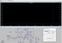
It was alright when I tested with LSK389 or LSK170. But lets Spice it also.
I'm a little confused by that Bode plot. You have 70 degrees of phase margin at the zero-gain point which is great, but virtually no phase margin around 1 Mhz...
Or maybe I'm forgetting my electrical engineering theory. It's been nearly forty years since I sat in a EE classroom.
-Henry
- Home
- Source & Line
- Analog Line Level
- Salas DCG3 preamp (line & headphone)