Still safe for heat. When not in a box at least.
P.S. Also wire the pot's metal to the GND main trace on the board. To one HP connector's GND screw maybe which is handy right now.
Okay? - You mean the shaft ?
Jesper.
You can probably find space for a thin enough wire where the pot's body is fixed on the bracket. Jammed between frame and nut or add a thin extra like a ring from an RCA with an ear to solder a wire. There is an unused eyelet to the bracket's left also. Or wire to a front alu-bar screw. Anything that will make the pot's metal body show continuity to the other grounds.
You can probably find space for a thin enough wire where the pot's body is fixed on the bracket. Jammed between frame and nut or add a thin extra like a ring from an RCA with an ear to solder a wire. There is an unused eyelet to the bracket's left also. Or wire to a front alu-bar screw. Anything that will make the pot's metal body show continuity to the other grounds.
Your'e genius

It actually took a loot of the hum!
Jesper.
Ooops... Now Tea will face riot to cut off the DCG3 GB part from the rest and close it
Ooops... Now Tea will face riot to cut off the DCG3 GB part from the rest and close it
Ha... Your'e the chief moderator, you could ban me
...Anyway its been playing for an hour or so now, still sound good and no problems at all. All hum are nearly gone now!
-My B1 bufferamp, also not having the shaft/metal connected; il'l bet the hum also dissapears from that, if i do the same?
Btw. Forgot to tell, that i set gain at 2x (499ohm)
Jesper.
Yes do the same. When a pot's metal part case is not grounded it acts as a magnet for AC fields. If also now after an hour with no real heatsinking still has about 100mA, then its not just steady bias, its stubborn mule grade bias
Hi.
I will try it when i am done listening
-After i bring it back to my desk.Jesper.
Play voices and big orchestras too
Thumb up
I have to go to the theater with my work in short time. So unfortunately i dont have much more time now ( maybe i also need a break )...
Have a nice evening on this rainy saturday here in DK
Jesper.
See ya!Thumb up
I have to go to the theater with my work in short time. So unfortunately i dont have much more time now ( maybe i also need a break )...
Have a nice evening on this rainy saturday here in DK
Jesper.
Yes, I loved the drums. The whole thing actually.
Teabag does not fear the rioting. He encourages it.
Yes, I loved the drums. The whole thing actually.
Teabag does not fear the rioting. He encourages it.
Yes
I am trying to draw the layout, which i will try regarding grounding.
(I know it can differ between builds)
Will it be a good idea to keep power and signal grounds separated ?
-See picture.
Normally i use twisted-pair's for interconnection, but the buildguide suggest the possible use of shielded cable. By shielded cable, you mean 2 wires + screen cables?
So if decided to try out shielded cables, then shield have to be connected only at "incomming/source" end (Otherwise they act as antenna). By that i mean if using stargrounding that shield have to be unconnected/open at starground point?
And ofcause remember to connect metal/shaft of the desired potentiometer (thanks Salas)
Jesper.
Attachments
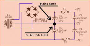
Mains earth goes to a chassis secure screw with a short cable from the IEC receptacle.
Use single core coaxial shielded cable one for each channel. Between switch or pot and pcb also.
Connect each shield both ways.
Avoid the reservoir capacitors common for referencing signal. Its a power ripple contaminated spot.
Try just a wire from the pcb ground strip to chassis. Lift it with 100 Ohm if its noisy. Bypass the R with 0.1uF.
Did you listen to more music? How's bias and temp on just the Alu-bar after long?
I agree with Salas.
Do not take the Mains PE wire to the transformer Centre Tap..
Do not take the Main Audio Ground to the transformer Centre Tap.
The Mains PE goes to Chassis at the mains input location.
The Main Audio Ground is connected to the PCB Power Ground.
That PCB Power Ground is fed from PSU Zero Volt, shown as 0V on your diagram.
If you have any exposed conductive parts, these should be connected to the protected Chassis. You can use the Transformer Centre Tap as your Safety connection to Chassis. This can be a direct wire link for a Mono-block build, or via Disconnecting Network for any multi-channel build.
Last edited:
Did you listen to more music? How's bias and temp on just the Alu-bar after long?
I took it down, before we went to the theatre
Klokkeren fra Notre Dame – The Musical – Fredericia TeaterLater today, i will fire it up again, i just have to make a thick aluplate for giving it some more sinking before i do. -I will post later.
Before i took it down, i tried playing some Celine Dion song's.. and eventhrough i only have an Ipad source, the voice was excellent. -I will not give any review yet through
too early for that!Regarding the grounding, i will study it more intensitivly. -No rush...
any good readings about grounding ???
Jesper.
- Home
- Source & Line
- Analog Line Level
- Salas DCG3 preamp (line & headphone)