[QUOTE= Do you have any same conditions THD plots with BA3 to compare?
After my last posting I did quite a bit of further listening. With my present setup I prefer the sound with around 15V rails. Really nice. If anyone wishes to give this a try all you need to do is short one of the ten block Leds of the DCSTB and you should be around 15.25v. Easily reversible.
Attached are the comparison plots of the DCG3bal/DCSTB at 15v and the BA3bal/ SSLV1.1 hotrod. I just did plots for both of them. 1V in and 0.56v out for the DCG3 and 0.58v out for the BA3 using the volume attenuator. Could you help me understand why I get a bit different levels of H2/H3 at different times even though THD and THD+N remain almost identical?
The overall sonic signature of both is almost the same. The DCG3 is slightly more dynamic with more clearly defined lower bass; the BA3 has smoother highs. I like them both.
Thanks for your help.
nash
Attachments
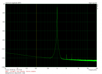
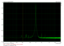
Maybe as the thermals kick in further you get differences of H2/H3 at different times. THD+N is a total so if noise and harmonics sum at a same amount even if with a different profile it remains the same number.
The plot to the right (dcg3) has significantly lower noise floor in the MIDS & LF except those little needles of interference. If they are part of the bench loop they are possibly smothered in the other plot. If not, but build's ground related, maybe you could try to seek and eliminate them. If Tx or other magnetic field related, more difficult.
Remains to also listen between preamps when both fitted with same number of alike PSUs i.e. shunts in your case.
Maybe as the thermals kick in further you get differences of H2/H3 at different times. THD+N is a total so if noise and harmonics sum at a same amount even if with a different profile it remains the same number.
The plot to the right (dcg3) has significantly lower noise floor in the MIDS & LF except those little needles of interference. If they are part of the bench loop they are possibly smothered in the other plot. If not, but build's ground related, maybe you could try to seek and eliminate them. If Tx or other magnetic field related, more difficult.
Remains to also listen between preamps when both fitted with same number of alike PSUs i.e. shunts in your case.
Thanks Salas; I always learn something from reading your posts.
In your experience why would the plot on the left have the higher noise floor under 1k caused by? Preamp circuit, PSU Tx?
nash
Its input JFET types are low noise so it can't be due to those. The noise level rise is smooth without interference peaks also. I don't know if it could be something in the build or inherent to the design like the impedance of the output coupling capacitor, or possibly less PSRR than DCG3's. I would gravitate to first guess on the 10uF capacitor's impedance. But it takes a real analysis to surely say.
Changed over the volume pot to a remote controlled TKD 2CP-2511 and I'm using a cheap chinese motor control board like this to drive it.
First thing I noticed with the TKD is how much more travel there is on the pot at lower volume, I guess this is just down to the curve TKD have used. For this alone it's a big plus. Sound wise it's night and day. Harshness gone, poor soundstage gone, poor imaging gone.
Only thing I've noticed is there is a very faint ticking noise from the speakers when I adjust the volume using the remote - any idea how this noise is getting in to the audio path? I'm using the 12V out on the iSelect to supply the controller board for the TKD. I've kept all the wiring for the controller board well away from any audio wiring.
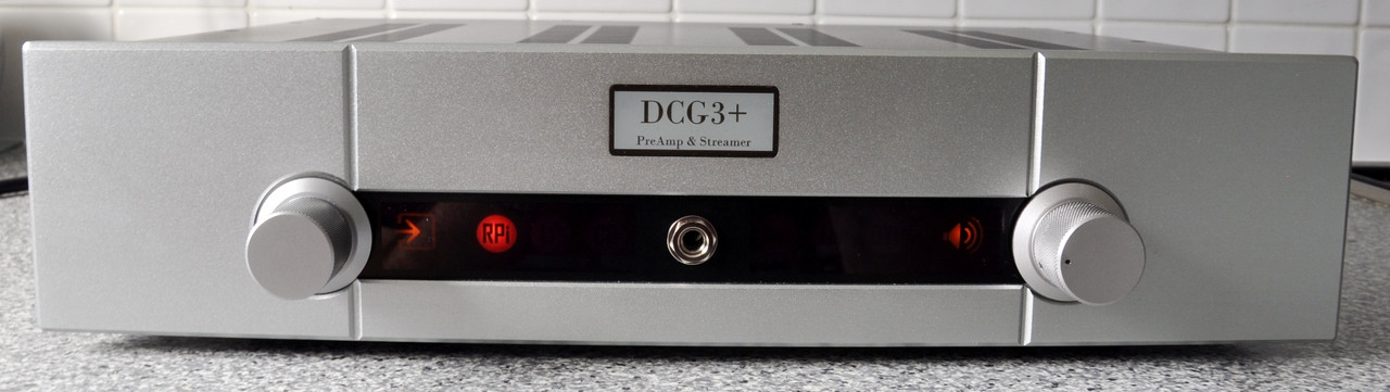
Finished DCG3 .... need to find a new project for the winter.
First thing I noticed with the TKD is how much more travel there is on the pot at lower volume, I guess this is just down to the curve TKD have used. For this alone it's a big plus. Sound wise it's night and day. Harshness gone, poor soundstage gone, poor imaging gone.
Only thing I've noticed is there is a very faint ticking noise from the speakers when I adjust the volume using the remote - any idea how this noise is getting in to the audio path? I'm using the 12V out on the iSelect to supply the controller board for the TKD. I've kept all the wiring for the controller board well away from any audio wiring.
Finished DCG3 .... need to find a new project for the winter.
You were right seeking a better pot after all. Congrats.
The very faint ticking noise when remote controlling the pot's motor could be coupling through the input board's ground as it powers your remote board which then powers & controls the motor. That same line powers the input relays.
The very faint ticking noise when remote controlling the pot's motor could be coupling through the input board's ground as it powers your remote board which then powers & controls the motor. That same line powers the input relays.
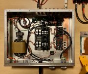
Yes, eBay purchased aluminum-junk alloy lid does make electrical connection to Earth GND chassis. Strange that it is only left channel is susceptible for that reflection of Tx stray. If it is still below 105 dB in any way, does it make sense to try to use Mu-Metal sheets or some Fe trany covets to attenuate Tx flux? Or it is just unnecessary perfectionism to satisfy placebo?
Is the left channel nearer to the Txs in your build?
Yes it makes some sense to experiment with mu metal sheets for barrier or dressing.
Surely for technical satisfaction and maybe for a wee bit of more clarity? But then you would know.
Can you post the lid off & lid on now FFTs?
Yes it makes some sense to experiment with mu metal sheets for barrier or dressing.
Surely for technical satisfaction and maybe for a wee bit of more clarity? But then you would know.
Can you post the lid off & lid on now FFTs?
Is the left channel nearer to the Txs in your build?
Yes it makes some sense to experiment with mu metal sheets for barrier or dressing.
Surely for technical satisfaction and maybe for a wee bit of more clarity? But then you would know.
Can you post the lid off & lid on now FFTs?
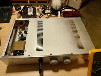
My left channel is located farther from Tx vs. right channel.
Please see test results attached.
I tried to be as detailed as possible there.
I took out my small Tx (witch dedicated to iSelect) for troubleshooting purposes and did not see any impact with or without it. So, it is not one that involved. I also used smaller aluminum cover to simulate partial lid and the effect starts to be obvious when I cover DCSTB from the top. Left or right enclosure sides coverage with that small lid are not effected left channel noise.
Attachments
The general results are very good. Still... Don't push the audio interface to 0dBFS because it adds enough of its own THD. Keep it at -6dBFS. Also use 48kHz sampling because 192kHz bumps the interface's noise over 30kHz. Upscale the FFT points in ARTA to 65536 or even better to 131072 if the PC & interface are fast enough. So to see the noise floor better and any spikes better.
Response isn't naturally down not a bit at 20kHz. It must be a trait of the interface or RightMark software & hardware related or something with long high capacitance test cables and interface Zout. DCG3 on gen & scope goes -3dB at 2.9MHz without a pot and 800kHZ-1MHz for 20K pot at half level attenuation worst case point.
Has 107nS rise time for 1kHz square wave when without using a pot (i.e. at 50Ω gen source impedance straight in).
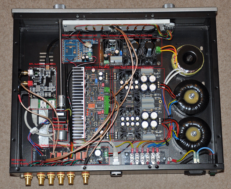
See about the cabling first. Especially the line out route take it close to the chassis floor firstly. Its closest to the lid now. Try shielded cable for the line and headphone output routes too if no better with moving as they snake around a rather long way.
To control what interference the lid sends to the left channel, experiments with Mu Metal sheets could help. Maybe a cover for the preamp board itself, or a barrier around it, or lining of the lid, or the selector & connectors are the pick ups to protect, you will see.
Response isn't naturally down not a bit at 20kHz. It must be a trait of the interface or RightMark software & hardware related or something with long high capacitance test cables and interface Zout. DCG3 on gen & scope goes -3dB at 2.9MHz without a pot and 800kHZ-1MHz for 20K pot at half level attenuation worst case point.
Has 107nS rise time for 1kHz square wave when without using a pot (i.e. at 50Ω gen source impedance straight in).
See about the cabling first. Especially the line out route take it close to the chassis floor firstly. Its closest to the lid now. Try shielded cable for the line and headphone output routes too if no better with moving as they snake around a rather long way.
To control what interference the lid sends to the left channel, experiments with Mu Metal sheets could help. Maybe a cover for the preamp board itself, or a barrier around it, or lining of the lid, or the selector & connectors are the pick ups to protect, you will see.
I'll re-run with 48kHz tomorrow. RMAA is not stable with Win 10 and it takes some effort to force it to run. Min dBFS is -3,5 and otherwise it will not start the test. I'll also go for that level during next test.
You're right and my current cables are not "something". Also I have several adapters from RCA to 6.35mm. All these all together probably adding some high pFs. My pot is 25k. Unfortunately, not Goldpoint and not Khozmo are making these with 20k values.
I'll experiment with Permalloy. I'll report soon.
- Home
- Source & Line
- Analog Line Level
- Salas DCG3 preamp (line & headphone)