For a line output 2nd stage VAS grade types like KSC3503 KSA1381 150MHZ biased at 10mA would be sufficient I guess. Very linear with very low Cob, Cre. I have such in the SSHV2 HV shunt PSU. You already use a cousin the KSA992 little guy by the way. Those two I mentioned for push pull output are even faster and can handle far more mA than the little cousin but with far lower Hfe than him.
")
Hi Salas,
I would like to experiment in changing H2 in my build. What circuit value can I play with? I am thinking perhaps R3? It is presently at 221r as supplied by TeaBag for the J3 he also supplied.Maybe something else?
While you have specified a 17v supply you have also indicated somewhere in this thread that even upto 23V is fine if it wasnt for the U1 voltage limitation. Conversely, how low a voltage could one use?
Thank you.
nash
Hi
There is no mechanism to play with the harmonics.
The 12V relay has must operate voltage spec of 9V and the three LEDs drop 5V to it so 9+5=14V minimum safe rails for all systems to operate correctly. If you short a LED or more, requirement goes further down until 9V rails.
U1 is also OK with that because it has a wide rails voltage operation spec (+/-1.5V to +/-18V for AD823).
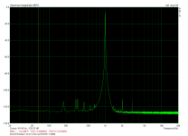
First I changed DCSTB output to 18.5v and gave it a listen. A bit harsher than before; Focusrite showed that H2/ H3 was now about 1db lower than at 17v. Then I made it 15v and listened. Very nice. Notes were fuller than before(compared to 17v)with no apparent lessening of detail. Focusrite showed H2/H3 over 1db higher than the 17v version. 1db does not seem much but subjectively does what the doctor ordered. I dont feel any need to have more H2. The left chart is at 17v, the right at 15V both fed 1v balanced 1khz sine and balanced output of 0.56v.
What I would like is the greater ambience that my BA3bal has, but that has the hotrodded SLV1.1. Waiting to get the Ultra Bib from TeaBag. I think that will do it.
I also plan on trying out the 2SK170BL or the LSK389B. How close an Idss match do I need on the 2SK170's?( LSK389B datasheet notes indicate that they are matched within 10%). Do the Idss's need to be the same for the LTP's of both channels?
Thanks.
nash
Attachments
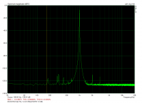
At 15V the sound becomes somewhat rounder, I have also heard that during the SE normal build's development. To my ears at 17V there was bit more neutral sound, but what is good and what is better its always a matter of preference and system synergy. BAL should behave bit differently as well.
At +/-18.5V rails a 36V spec U1 got too pushed also. Unless you used something like an OPA2604 which can go +/-24V.
Those are very good FFT plots, such little differences in an already very low amplitude THD profile are difficult to be directly audible in my experience. All FETS become progressively slower when the voltage across them is set lower within their first 25V because their capacitance increases. I would primarily think of that as a cause of subjective change. Easing the amp's rise time a little.
BTW weird there is 180Hz in the grass without a 60Hz fundamental. Those little spikes don't seem harmonically related other than the 320Hz and 640Hz needles. Maybe they show up in your measurement loop due to some non mains related factor. Very minor anyway. They add the same to the THD+N indication in both cases.
UBiB will give some presentation differences but to match the BA3 sonic in an area and keep the DCG3's in another its a juggling act. Not close designs but I wish you success. Do you have any same conditions THD plots with BA3 to compare?
If you will IDSS match K170s they should be as close as in any amp's differential input pair. 10% max I would say. The diyA store prepared some +/- 0.1mA LSK170B quads for the Mezmerize DCB1 "Ten Years After" edition. Translates to +/-1.2% in 8mA. Those should do very well here too I would think.
There was 10K load in the sim. But driving its own feedback resistors is 750 Ohm already, then the output is in parallel.
By the way, the usual PC audio interfaces in BAL output jack mode don't output two opposing signal phases i.e. double the signal voltage at 180 degrees but merely impedance balanced same peak to peak voltage output as much as in their SE output connection mode. Their rails and dBFS don't have the headroom for handling double the signal.
By the way, the usual PC audio interfaces in BAL output jack mode don't output two opposing signal phases i.e. double the signal voltage at 180 degrees but merely impedance balanced same peak to peak voltage output as much as in their SE output connection mode. Their rails and dBFS don't have the headroom for handling double the signal.
For heavy loads capable of soaking all the bias current see post #79. As the current ends, the positive portion can swing double than the negative. Because this is not a push pull but an SE output stage with a fixed amount from a CCS FET in the negative. That's center point in the pos but end stop in the neg. So the voltage clip will start only in the negative part until the positive goes finally out of current swing too. This condition is relative when dummy load testing for certain headphones impedance max voltage swing available.
- Home
- Source & Line
- Analog Line Level
- Salas DCG3 preamp (line & headphone)