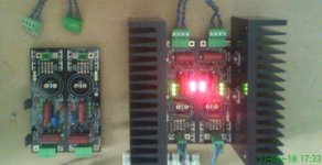
All set for my DCG3 to be fired up with all the parts installed and mosfets drilled and tapped on a good size heat sink. Also the BiB was setup to +/-17V DC very stable voltage using the new EI cores (18v) transformer and it runs cool, thanks for the suggestion Salas. I used a 150R 5W wirewound resistor as the load resistor for +/-IRF to set the voltage. Now that all mosfets look perfectly aligned to the heat sink will solder the pins. Checked the shorting of the mosfets to the heat sinks and all looks fine with the TO-220 insulation pads and small plastic bushes which came with Tea-Bag.
Here are the pics:


Here are the pics:
Last edited:
I just powered it up and the DCG3 all the 3 LEDs lit and within a few seconds the relay clicked and everything looked stable without any heating up issues.
A quick question regarding the DC voltages after powering up the DCG3 board with +/-IRF boards. I used the 150R 5W as load resistors and set the output DC voltage to a very stable +/-17V. Now after I connected the PSU to the DCG3 board and measure the voltages, either on the preamp board or directly on the PSU boards I get the positive being at around +16.98v but the negative side shows a dip in the voltage at -6.19v.
Is it normal or do I need to increase the PSU voltage on the negative board to -17V DC again now with the preamp board connected?
Thanks
Edit: Apart from the DCG3 preamp board even the Salas source selector board is also powered from the +,0 of the +IRF board. So right now only 2 boards are being fed from the +/-IRF BiB boards.
Last edited:
For starters, are you sure that your BiB's positive and negative rails are both set for the same CCS current? On the BiB the positive and negative rails need different CCS setting resistors to obtain same CCS currents.
Do you have some other power supply to use for testing the DCG3?
Do you have some other power supply to use for testing the DCG3?
One of the channel the voltage drop across R10 shows correctly at 48mV but the other channel starts at 2.19v and stays there which is against the guide that it should be within 100-150 mA. Seems to be some problem with one of the channels.
Maybe the DN2540 connected to that high voltage drop R10 is shorted. Either to chassis or it died during handling & assembly. Luckily the BiB limits any fault current in the preamp to its own CCS setting thus it drops the rail voltage and controls the damage. Like lab supplies in CC protect mode do. You look for 1.2V or thereabout across each R10 after you will fix the error. Measure those R10 for Ω value also.
I just checked the Ra+ and Rb+ ohms and realized that the Rb+ shows on the DMM as 1.6R instead of the 15k as per the guide. This check I am doing it with the resistor soldered to the board. Is this the issue?
The Ra+ shows correctly at 68.1K.
Edit: I lifted one leg of Rb+ and rechecked and its fine with 15k.
The Ra+ shows correctly at 68.1K.
Edit: I lifted one leg of Rb+ and rechecked and its fine with 15k.
Last edited:
Maybe the DN2540 connected to that high voltage drop R10 is shorted. Either to chassis or it died during handling & assembly. Luckily the BiB limits any fault current in the preamp to its own CCS setting thus it drops the rail voltage and controls the damage. Like lab supplies in CC protect mode do. You look for 1.2V or thereabout across each R10 after you will fix the error. Measure those R10 for Ω value also.
Hmm need to check DN2540 but if its damaged then thats a big issue as Tea-Bag provided matched VGS
 . I checked for shorting for all the mosfets before powering up and they are perfect insulated from the heat sink.
I checked the resistances across the legs of the DN2540 and both of them look exact same with perfect matched values. So I hope the mosftet M3 on this side of the channel looks fine. Do I need to check anything else to resolve this issue.
I will use the 150R 5W load resistor again and check the BiB voltages if that seems to be an issue or not.
The R10 I have used is 12R on both the sides.
Disconnect the BiB and test its polarities with dummy loads again. To see they still work well alone. Let us know Vdrop and value of your BiB setting resistors. Compare DCG3 components per position between sides while the PSU is disconnected.
Hmm let me check this as I used small shorting pins on the BiB output sides to make it regular 2 wire outputs rather than Kelvin types. So when we short with pins I presume it does not make a difference with which side I am going to run the output wire? Or does this make a difference?
Hmm let me check this as I used small shorting pins on the BiB output sides to make it regular 2 wire outputs rather than Kelvin types. So when we short with pins I presume it does not make a difference with which side I am going to run the output wire? Or does this make a difference?
Does not matter. But maybe the pins press together and short -F to 0?
Your guess looks correct on the BiB negative board Salas, I see that the Q205 is reversed on the negative board. Those small transistors are hard to see the orientation if not done carefully. I think this reverse makes the polarity correct. As the positive board has this the opposite and looks fine with my orientation as well. Hence the positive side gives the output correctly but the negative one might be actually giving wrong polarity.
Yep, for one side the polarity is reversed, so it's
DCG3 --- [ - 0 + ] and [ + 0 - ]
BIBs ----- [ -0 0+ ] and [ -0 0+ ]
This build is gonna be a two box implementation and currently I can't move it from rack so to take a picture of it, but here is a photo of BIBs in early stage
Bias 100mA
CCS 350mA
I think I'm gonna add a local decoupling cap (PP) later on
I'll check for any anomalies you suggested next time I pull it out of rack. Last thing I've done is a 2 in 1 waveform comparison (one waveform on the top of the other)
Input was fed by generator with 1kHz / 10kHz at variable level -8 / +2 / +12db / +22 dbm. The output looked identical in oscilloscope. Wish I had the GB analyzer
Attachments
Thanks Savvas, I hope that once I reverse the Q205 on the negative board I should get the proper polarity and then I will set the output voltage again on both the boards using the 150R 5W load resistor to get to +/-17V DC and power the DCG3 again. I hope nothing has damaged on the DCG3 board , as desoldering any parts on the DCG3 looks like a pain with so many small parts.
, as desoldering any parts on the DCG3 looks like a pain with so many small parts.I assume that you have the Tea Bugs boards, there you can easily see what's the right orientation for Q205 by looking at the screen layer of pcb.
Yes, QX03, QX04 and QX05 is the first transistors to check if the two leds near trimmer are light up and you have problem with voltage setting.
Don't worry, most probably mosfets survived this, just check the jfet and replace it if necessary
Yes, QX03, QX04 and QX05 is the first transistors to check if the two leds near trimmer are light up and you have problem with voltage setting.
Don't worry, most probably mosfets survived this, just check the jfet and replace it if necessary
I reversed the Q205 on the negative BiB board and checked the DC output voltage with the load resistor. As you can see from the below pic I still do not see the '-' sign on the DMM for the yellow cable which is for the negative board.
But if I change the probes of the DMM then I get to see the '-' sign for the DC output voltage. So not sure where exactly is the problem for the BiB boards.
An externally hosted image should be here but it was not working when we last tested it.
But if I change the probes of the DMM then I get to see the '-' sign for the DC output voltage. So not sure where exactly is the problem for the BiB boards.
An externally hosted image should be here but it was not working when we last tested it.
Does not matter. But maybe the pins press together and short -F to 0?
Stupidity of me to connect the wrong colored shorting pins on the negative board
. Now the negative voltage shows up correctly after I found that with the DMM probes reversed the voltage was becoming negative. Let me now connect to the DCG3 and hope nothing would have happened to the preamp board Now Q205 looks in the right way. Your yellow cable is the 0 and the black is the - (negative board)
I assume that you are using one bib for both negatives (i.e. both channels) and the other for positives
In that case you have to join all the 0 of both boards together
If your positive board has black for 0 and red for +, you have to join the yellow from negative and black from positive together. It would have been for appropriate to have used the colors in your negative the other way (yellow for -), so all black cables were connected together.
Always first check with both load resistors before connecting DCG3
Good luck
Last edited:
Yes it looks fine now with the first power up and I get around 1.2v on both the R10's and mosfets are slowly getting warmer.
Now looking at the guide it says "after shorting the signal inputs and measure the DC offset across each line output". This means that I am going to use this preamp for both line as well as HP duty. So I need to test the DC offset and make it 0mV or closer to that on both the line output and HP output individually?
Now looking at the guide it says "after shorting the signal inputs and measure the DC offset across each line output". This means that I am going to use this preamp for both line as well as HP duty. So I need to test the DC offset and make it 0mV or closer to that on both the line output and HP output individually?
- Home
- Source & Line
- Analog Line Level
- Salas DCG3 preamp (line & headphone)