yikes!

what version of diptrace are you using where you see this error?
mlloyd1
what version of diptrace are you using where you see this error?
mlloyd1
...
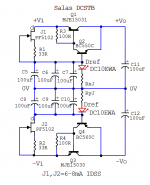
But what do you think of the DipTrace having the Drain where the "Gate-arrow" is ??? Funny thing. Am i not right here?
...
Rgds; Jesper.
Hi.
Does this layout look any better Salas ?
Btw. : Can you post the PCB layout of the psu?, like you did with the preamp pcb?
Good evening all. Jesper.
Jesper,
What is the size of your amp PCB? I think I can do it point to point but my headphone amp chassis is limited in size.
Thanks.
yikes!
what version of diptrace are you using where you see this error?
mlloyd1
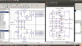
Here you go :
Latest build: 3.0.0.2 (June 14, 2016). Supported OS: Windows XP / Vista / 7 / 8 / 8.1 / 10; Linux (Wine); Mac OS X (XQuartz X11 required).
This is the only fail, i ever did find in this excelent program through
Jesper
Jesper,
What is the size of your amp PCB? I think I can do it point to point but my headphone amp chassis is limited in size.
Thanks.
Preamp approx. 190mm x 80mm
PSU 90mm x 120mm.
Jesper.
Evening all ...
I am confused, so i need you guy's to help me a bit if possible!
Last night i was comparing the PSU layout, which Salas did, and the layout i do right now.
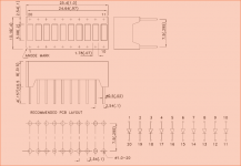
The component DC10EWA https://www.google.dk/url?sa=t&rct=j&q=&esrc=s&source=web&cd=1&cad=rja&uact=8&ved=0ahUKEwjZx6jVg9PPAhWC7hoKHWVoBM4QFggwMAA&url=https%3A%2F%2Fwww.kingbrightusa.com%2Fimages%2Fcatalog%2Fspec%2FDC10EWA.pdf&usg=AFQjCNFeSST4TPkaGZuZgHXyWQUhJ67Enw i created inside my pcb program, according to the datasheet.
But when i look at my pcb-design, i see that Salas's pcb is connected differently to DREF1 and DREF2... according to my component and datasheet, my schematic is correct, and salas has swapped anode/kathode connections.
Well... i surely belive that Salas is the correct one ... But i cannot figure out, what is wrong with my connections.
Please help me, before i go nuts
(On my schematic i have not yet connected the series zigzag connection inside DC10EWA)
Jesper.
... I am confused, so i need you guy's to help me a bit if possible!
Last night i was comparing the PSU layout, which Salas did, and the layout i do right now.
The component DC10EWA https://www.google.dk/url?sa=t&rct=j&q=&esrc=s&source=web&cd=1&cad=rja&uact=8&ved=0ahUKEwjZx6jVg9PPAhWC7hoKHWVoBM4QFggwMAA&url=https%3A%2F%2Fwww.kingbrightusa.com%2Fimages%2Fcatalog%2Fspec%2FDC10EWA.pdf&usg=AFQjCNFeSST4TPkaGZuZgHXyWQUhJ67Enw i created inside my pcb program, according to the datasheet.
But when i look at my pcb-design, i see that Salas's pcb is connected differently to DREF1 and DREF2... according to my component and datasheet, my schematic is correct, and salas has swapped anode/kathode connections.
Well... i surely belive that Salas is the correct one
... But i cannot figure out, what is wrong with my connections.Please help me, before i go nuts
(On my schematic i have not yet connected the series zigzag connection inside DC10EWA)
Jesper.
Attachments
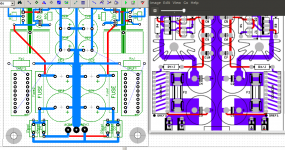
Led blocks and Rx,y swapped positions in the boards vs shown in the schematic for same length tracks left & right. Because in series its the same circuit result.
Thank's...
I simply cannot see, why it's the same ?
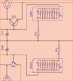
If i swap resistors to be on the other side of the LED block (See attachment), the pcb layout will be the same as yours.,
But if i follow the original schematic, i cannot make that layout, no matter how i do it ???
sorry for the confussion
Jesper.
Attachments

I just found this :
I feel so stupid... i allway's thought, that resistor must go on positive side of LED, else it wouldent work... so embarrising
Sorry for all the confussing here!
Jesper.
It doesn't matter if place the resistor before or after the LED because is the amount of current the resistor limits as not to burn the LED. In a series circuit the current is the same for all components and because the LED and the resistor are in series you can connect them as you want.
I feel so stupid... i allway's thought, that resistor must go on positive side of LED, else it wouldent work... so embarrising
Sorry for all the confussing here!
Jesper.
Nice work Salas. After reading the PDF it's next on my list of things to build.
Thanks. You usually make a hardwired attempt if I remember well, like Tham.
Thanks. You usually make a hardwired attempt if I remember well, like Tham.
I'm cheap, but something like this might be easier to do on a PCB with all the relays and such. But I think you learn more by doing point to point, you actually realize what the parts are doing.
But if this thing is anything like your phono stage it will be worth it.
I'm cheap, but something like this might be easier to do on a PCB with all the relays and such. But I think you learn more by doing point to point, you actually realize what the parts are doing.
But if this thing is anything like your phono stage it will be worth it.
Its about ready and handy with hardwiring, not being cheap. To really finish this preamp in a box, not even too luxuriously with heavy construction and great connectors, fancy big trafos, super resistors, fine quality pot or LDR, Arduino remote ladder board & color screen etc. but just decent industrial stuff, and although it needs no coupling caps or myriads of components, it will eat way way more money till then anyway.
BTW Michael phoned late yesterday and said that his conclusion is that the superiority he felt over his beta builds and he was perplexed about is the pcb itself after all in his opinion because he tried one I gave him (I had only two spares) and all other things he did were not more influential. So if you hardwire its not bad to try follow the pcb's general idea. Its true that I had bugged Crt's life with my guides & revisions for quite a while though. Sorry Crt
Ok, I have started the process of opening a GB for all Salas boards including these.
The sign up spreadsheet is linked in my signature. (Please don't post here). The board prices are fixed, but the kit prices are not quite solid yet, as I need to line up a few items cost before fully disclosing that. So I hope to have that done ASAP, but feel free to sign up in spreadsheet to show your interest. Once pricing is finalized, I will start a GB thread that mostly focuses on getting boards and parts. Let me know if there is any problems with sign up. The DCSTB boards are on the far right. You will need to scroll over unless your using a 4k monitor!
The sign up spreadsheet is linked in my signature. (Please don't post here). The board prices are fixed, but the kit prices are not quite solid yet, as I need to line up a few items cost before fully disclosing that. So I hope to have that done ASAP, but feel free to sign up in spreadsheet to show your interest. Once pricing is finalized, I will start a GB thread that mostly focuses on getting boards and parts. Let me know if there is any problems with sign up. The DCSTB boards are on the far right. You will need to scroll over unless your using a 4k monitor!
Ok, I have started the process of opening a GB for all Salas boards including these.
The sign up spreadsheet is linked in my signature. (Please don't post here). The board prices are fixed, but the kit prices are not quite solid yet, as I need to line up a few items cost before fully disclosing that. So I hope to have that done ASAP, but feel free to sign up in spreadsheet to show your interest. Once pricing is finalized, I will start a GB thread that mostly focuses on getting boards and parts. Let me know if there is any problems with sign up. The DCSTB boards are on the far right. You will need to scroll over unless your using a 4k monitor!
Tea Bag,
will the board be included in the full kit ?
will the uPA68 be included in the transistor or full kit ?
It may be convenient to have them as an option of the transistor kit and full kit as some DIYer may already have them in stock or may want to try LSK389 or 489.
thanks for all, I was very happy with the execution and the parts quality of your last GB !
Hi there! I just couldn't help myself but to sign in to the group buy for one DCG3 transistor kit and one power supply kit. Excellent design and documentation by Salas and great that Tea-Bag is organizing this group buy. I have absolutely no idea where to stuff yet another hifi equipment, but this is truly something I can't skip!
P.S. @Tea-Bag: I removed myself from the Salas LV power supply GB.
P.S. @Tea-Bag: I removed myself from the Salas LV power supply GB.
Last edited:
- Home
- Source & Line
- Analog Line Level
- Salas DCG3 preamp (line & headphone)