Hey (Salas)
I have one quistion, about the pcb layout.
Actually this is (i think) the only point, where i am in little doubt :
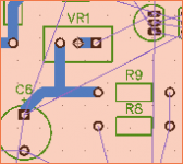
If i look at the schematic, there is connection between top of VR1 -> Q2 -> R9 -> C6 and M1.
I got those connections, when i am making the pcb.
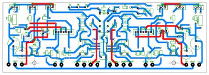
But if i look at youre pcb, i can't directly see connection between those 4 parts, unless as i assume, that the toplayer (red?) and buttonlayer (blue) is connected at left side of R9 !
Am i right ? (Think i am )
)
Rgds; Jesper.
Btw. : Sry. that i "copycat" the layout
I have one quistion, about the pcb layout.
Actually this is (i think) the only point, where i am in little doubt :
If i look at the schematic, there is connection between top of VR1 -> Q2 -> R9 -> C6 and M1.
I got those connections, when i am making the pcb.
But if i look at youre pcb, i can't directly see connection between those 4 parts, unless as i assume, that the toplayer (red?) and buttonlayer (blue) is connected at left side of R9 !
Am i right ? (Think i am
)Rgds; Jesper.
Btw. : Sry. that i "copycat" the layout
Attachments
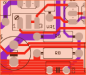
That's the positive rail parts connections going along the +Rail blue line in other words. But VR1 & Q2 get it from the plated canal at the components side R9 left pad. Its soldered leg makes a strong bridge in the end. Don't be afraid following your layout ideas suiting better for your box floor plan or favorite parts and their sizes, no worries.Hey (Salas)
Am i right ? (Think i am
Rgds; Jesper.
Attachments
Hi Salas,
Do both channels share the same gnd?
Wouldn't better to have separated?
I had them separate on the proto to check that out and did tests with and without a cable jumper bridging the extra outer blue pads at the bottom. I saw no difference in hum for common and double PSU (when all was connected up and chassis grounded through the input's returns at the pot) so I closed the gap for the common op-amp's ground reference to be as close to both channels.
Attachments
Is the relay closing time set to a specific time or is it adjustable?
Every 10K about 1 sec. I have 68K Ra now just in case some turn on DC bumps are slower to cycle. I heard nothing different "plop" (which was pretty much nothing anyway) during power up than before (51K) when testing cranked up on headphones, but again, just in case. Nobody should be powering up or down any preamp when the power amp is on as a general good practice nonetheless.
Nobody should be powering up or down any preamp when the power amp is on as a general good practice nonetheless.
Yeah, I know that but others may not.
I never apply power to a preamp/buffer after the power amp is on.
I can live happily ever after without muting circuits(except on power amps) or switched inputs.
But since you incorporated it onto the board, I thought I would ask. I'm quite surprised how simple the muting circuit is.
Any word on pricing for the preamp boards? I asked several posts back, but I guess tea bag, or whoever is doing the boards, didn't reply.
Thanks.
I asked him many days ago if it will be at less than the Hypno which is somewhat bigger but I would like it in matte black also and he said possibly if there are enough pcs but it takes a week more for that color. Which means around $20 for the dcg3 pcb if I did not it blow it with the little changes I sent him for both the preamp and psu which also means retooling. I.e. additional costs and time.
I would like it in matte black also and he said possibly if there are enough pcs but it takes a week more for that color.
Black, red, blue, etc. boards are usually more expensive with most board houses that I've dealt with, but the turnaround time is usually the same.
He must be dealing with some non-Asian board house.
Nonetheless, I'll pay $20 for a single board to try when they're available.
Thanks for your reply Salas.
A small relay will open, or close, in around 1ms to 5ms. That's without a reverse current diode across the coil.Is the relay closing time set to a specific time or is it adjustable?
A big relay could be around ten times slower.
If you add on a reverse current diode, then those that have measured it seem to indicate that the opening/closing time very roughly doubles.
Adding in the resistor and/or Zener reduces that ~doubling, but never gets back to the no diode times.
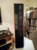
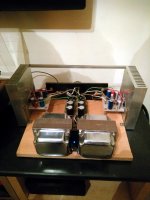
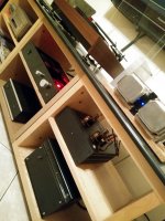
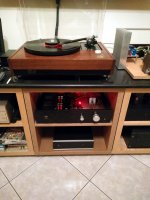
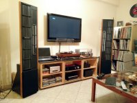
My DCG3 is boxed and back in my hands now. Thanks to the mechanical skills of my friend Michael who turned a cheap aluminum box of almost industrial looks to a nice housing with a perspex front and fitted the PCBs orderly inside. We listened to it in his system for long too. It can be seen sitting in the middle under his vintage and highly modified Walker CJ55 TT which is running on DC motor. The Jelco arm that he transformed with a carbon wand and DIY counterweight looks and tracks super with the Benz Ace cart. There is also a USB enabled Mambo ES9023 DAC sitting bellow the preamp. A Valve Itch phono stage and a Juma's Cubie2 amp in open frame style are situated to the right. Eminent Technology LFT-8 speakers are flanking the equipment rack. They look like the 8b model because they went through laborious modifications that included placing the HF unit lower.
Attachments
Salas.
Looking very pleasant, your'e freinds gear
Well... I will be done with my preamp software-layout in a couble of day's (I think), so next project will be the psu.
I have at moment no headphones, but i would like to make the preamp capable of driving fancy ones, if i ever got some.
Do i need 1 or 2 psu's then ?
The picture i have attached, shows 2 psu's right?
Jesper.
Looking very pleasant, your'e freinds gear
Well... I will be done with my preamp software-layout in a couble of day's (I think
), so next project will be the psu.I have at moment no headphones, but i would like to make the preamp capable of driving fancy ones, if i ever got some.
Do i need 1 or 2 psu's then ?
The picture i have attached, shows 2 psu's right?
Jesper.
Attachments
Drive in a heavy load is a matter of the output stage's current swing ability before clipping and not about mono psu or double mono psu. When you bias at 100mA with 17V rails it can give 156mW on 32 Ohm but when at 150mA it will be 360mW for instance. As you move to higher impedance cans it becomes more of a voltage swing thing than current. Both bias examples will do 400mW on 300 Ohm and 200mW on 600 Ohm when running on the same 17V rails.
Assuming that any supply arrangement chosen will be correctly covering the current demands that is. Two supplies is a quality choice to minimize the interaction of channels across a common supply. Especially when they are pulling high current peaks.
Our yesterday auditions were purely in line preamp's role where the output stage current swings are silly low anyway. For some reason this arrangement I prepared gives a subjective result that my friend maintains is easily better than with his beta build when he compared them on his own. There he has a tight matrix board layout, a single 500mA CCS shunt supply, two single op-amps, and a remote controlled pot. Both preamps run at same 100mA bias. Is it the different pots or the double DCSTB or the layouts or something else he is not sure at the moment but he will investigate his version better by building and comparing solutions as he said. Anyway one thing is certain, that the specific pre+psus pcbs system as developed arranged and proposed to be done in this thread are doing the business very well.
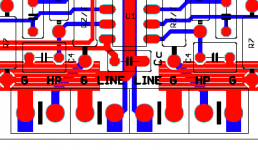
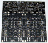
Yes the picture shows a two psus board (four polarities). The DCSTB board will be made as pictured plus two bleeder resistors I added across the front. One board but breakable in the middle. To can be arranged in a box to anyone's wish. I prefer them unbroken facing the DCG3 using short rail wires between them.
Assuming that any supply arrangement chosen will be correctly covering the current demands that is. Two supplies is a quality choice to minimize the interaction of channels across a common supply. Especially when they are pulling high current peaks.
Our yesterday auditions were purely in line preamp's role where the output stage current swings are silly low anyway. For some reason this arrangement I prepared gives a subjective result that my friend maintains is easily better than with his beta build when he compared them on his own. There he has a tight matrix board layout, a single 500mA CCS shunt supply, two single op-amps, and a remote controlled pot. Both preamps run at same 100mA bias. Is it the different pots or the double DCSTB or the layouts or something else he is not sure at the moment but he will investigate his version better by building and comparing solutions as he said. Anyway one thing is certain, that the specific pre+psus pcbs system as developed arranged and proposed to be done in this thread are doing the business very well.
Yes the picture shows a two psus board (four polarities). The DCSTB board will be made as pictured plus two bleeder resistors I added across the front. One board but breakable in the middle. To can be arranged in a box to anyone's wish. I prefer them unbroken facing the DCG3 using short rail wires between them.
The DCSTB board will be made as pictured plus two bleeder resistors I added across the front. One board but breakable in the middle. To can be arranged in a box to anyone's wish. I prefer them unbroken facing the DCG3 using short rail wires between them.
Salas... fantastic answer
Whatever i deside, i would like to have the two bleederresistors, on my DCSTB-board, if you would kindly care to show me, how they are attached!
And another thing. What about the DCG3 schematic, are there any changes to that, as for now?
... More quistions to come (for sure
)Jesper.
Schematics changes no. Bleeders go one across each output psu cap. After I will have also examined the rack ready preamp further as a system and my notes will be richer I will post a PDF that will have the schematics the boms and the practical points concentrated in one doc. As I promised from the start.
Hi here.
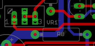
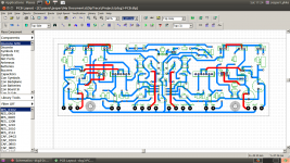
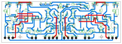
I did a clone of the PCB, it's layout is with "hand draw" in mind, so a little more space around traces/part is needed
About GND-plane (which isent drawn yet), i am in doubt, if it should be connected to GND ?
Also, is it something one do, for avoiding "hum"?
RED traces = TopLayer
BLUE traces = BottomLayer
all here have a good saturday
Jesper.
Attachments
The audio does not need to be connected to Protective Earth. Is that what you meant with GND?
The enclosure of mains powered equipment needs to be connected to PE for safety.
All exposed conductive parts need to be connected to that protected enclosure for safety.
Neither of these have anything to do with audio.
Get your audio circuits to work properly without any enclosure and without any connection to mains earth.
Then assemble your package so that it is safe to use.
i am in doubt, if it should be connected to GND ?
The enclosure of mains powered equipment needs to be connected to PE for safety.
All exposed conductive parts need to be connected to that protected enclosure for safety.
Neither of these have anything to do with audio.
Get your audio circuits to work properly without any enclosure and without any connection to mains earth.
Then assemble your package so that it is safe to use.
The ground plane is just a very wide trace that happens to cover the whole PCB.
If you have a separate ground trace on another layer then you need to connect these somewhere.
That chosen location must not force a trace to carry two different AC currents that could cause an undesired interaction between the voltage drops.
If you have a separate ground trace on another layer then you need to connect these somewhere.
That chosen location must not force a trace to carry two different AC currents that could cause an undesired interaction between the voltage drops.
- Home
- Source & Line
- Analog Line Level
- Salas DCG3 preamp (line & headphone)