The e/bay SUGDEN SDA-1 output buffer clone appears to be very faithful in topology. The signal path, servo IC and output transistor pair are as shown in the schematic. The JFET are 2 dual uPA58HA pack. The input stage current sink uses 2 2SC945. All seem to be reasonable equivalents.I am waiting for the delivery of a 3-stage line amplifier which clones the SUGDEN SDA-1 DAC output board and a low noise power supply.
Assembled HiFi Preamplifier Preamp Refer SUGDEN SDA-1 DAC For Amplifier Class A | eBay
AC-DC LM317 LM337 LF353 Servo Rectifier Filter Power Supply Module Adjustable M 783710088352 | eBay
View attachment 777083
The NE5534 is adequate for this board. But I will try LT1115 or LME49710 to see if I can hear any different in noise and other audio performance. The use of a DC servo instead of large output capacitor should be a plus in both sound and cost.
The PCB construction quality is very good. I have not fire it up yet.
High Speed IC Op Amp slew rate test
The e/bay board comes with NE5534 installed. If genuine, it should be adequate for its purpose. The LME49710 is quieter. The slew rate are 5V/microsec and 20V/microsec respectively which are nowhere near the 1000V/us. My purpose is to find out whether either one are genuine IC that meet the spec. Any suggestion on how to do the verification?
Mark, thank you for the tip and suggestion.The best way to test slew rate is to apply a square wave input with very fast risetimes and very fast falltimes. Unfortunately, a 100 kHz function generator is unlikely to give sufficiently fast edges.
If you use very short wires and lots of supply bypass capacitors, you can get 5 nanosecond risetimes and falltimes out of a 74AC04 logic inverter, even on a solderless breadboard. Since the AC family of digital logic gates has a 5 volt logic swing, that's 5 volts in 5 nanoseconds. Namely: 1000 volts per microsecond slew rate. Plenty fast enough to test opamp slew rate.
Build a little 1 kHz oscillator out of a 555 timer chip, buffer its output through a 74AC04, and apply those blazing speed edges to your amplifier through an AC coupling capacitor. Presto: the amplifier slews like the dickens.
_
The e/bay board comes with NE5534 installed. If genuine, it should be adequate for its purpose. The LME49710 is quieter. The slew rate are 5V/microsec and 20V/microsec respectively which are nowhere near the 1000V/us. My purpose is to find out whether either one are genuine IC that meet the spec. Any suggestion on how to do the verification?
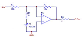
Maybe something similar to one of the circuits Samuel Groner used in his measurements, with a socket:The e/bay board comes with NE5534 installed. If genuine, it should be adequate for its purpose. The LME49710 is quieter. The slew rate are 5V/microsec and 20V/microsec respectively which are nowhere near the 1000V/us. My purpose is to find out whether either one are genuine IC that meet the spec. Any suggestion on how to do the verification?
This has overall unity gain but a noise gain of 60 dB for AC, so with a given reference level you should be able to do the math on whether input voltage noise is in the right ballpark (should be about 0.56 mV, 20-20k, so roughly -66 dBFS for typical onboard audio or -71 dBFS for a 2 Vrms input). Plus, you could determine its small-signal bandwidth @ -3 dB when running a signal over it, which should be a tad over 20 kHz, reduced when adding a small capacitor (e.g. 22 or 47 pF) between pins 5 and 8. Since the circuit is so slow, decoupling should be quite non-critical. If needed, you can always make it even slower by swapping the 10ks for e.g. 22k.
There aren't an awful lot of good candidates for fakes - maybe LF356 at best, but in bulk the difference between those and TI NE5534Ps is pretty marginal already (maybe 6 cents each - 5534s are not expensive parts). Anyway, these are not using pin 8.
BTW, this circuit as shown should be good for an output noise level of around 2.6 µVrms, or a good 117 dB below 2 Vrms. I hope that's good enough for a TDA1541.
")
Attachments
Last edited:
The Texas Instruments 5532 datasheet lists a slew rate of 9V/uS, not 5V/us (attached image.)The slew rates are 5V/microsec and 20V/microsec respectively which are nowhere near the 1000V/us.
For audio, the worst-case slew rate demanded of an op-amp is for a 30 volts peak-to-peak sinewave at 20 kHz. This is the biggest amplitude possible with the usual +/- 15V power supplies, and 20 kHz is the highest frequency that a normal healthy human ear can just barely detect at deafening (literally, ear damaging) volume.
If you calculate the maximum slew rate required to handle such a sine wave with no distortion, the answer is 3.77 volts / uS.
So the 5532 actually has more than double the slew rate needed to handle the worst-case audio signal. Your other op-amp has more than five times the slew rate needed for such a signal.
That is the engineering reality. Those are the facts.
The 1000V/uS number, on the other hand, is a fantasy, and a completely useless one. In fact, it's worse than useless, as this sort of vast increase in speed and bandwidth increases susceptibility to unwanted interference, and reduces amplifier stability. In short, you need 1000V/uS in an audio op-amp the way you need the proverbial hole in your head.
I find it sad that people have wasted their lives searching for a non-existent Holy Grail. I also find it sad when people waste time, money, and energy chasing an audiophile Holy Grail that's actually a rusty kettle full of rotten fish.
It's your life, your time, your money, your energy, so obviously, it's your decision what to do. That said, my two cents is to encourage you to enjoy either of the very nice op-amps you already have, and put the 1000V/uS recommendation where it belongs - in the trash bin.
-Gnobuddy
Attachments
What is the best way to test slew rate of these LME49710? Or the easiest way.
I have a 100KHz signal generator (Heathkit IG-18) and an Owon 100MHz oscilloscope.
The slew rate spec is 20V/uS. This is the maximum slope (at 0V) of approx. a 200kHz sine wave.
If the circuit can produce a 200kHz sine at the full 30V pp, as well as it does at 1kHz, that is
about 20V/uS. To allow for the swing limit of 1V from the supply, use 16 V supplies for the test.
You should be able to prod the Heathkit into a 200kHz sine.
Last edited:
> more than double the slew rate needed to handle the worst-case audio signal.
When it slews the NFB is -none-. When near-slew it is small.
We "should" aim for slew >> apparent need so that the top octave will be clean. Also so stray supersonics don't intermodulate.
Walt Jung claimed to hear "effect" if slew-rate was less than 1uS/Volt peak signal. If you run 13V peaks (as when near-clipping +/-15V supply) then you want >13V/uSec. If supersonics are present, general wisdom is you should low-pass them away.
Echoed by the fact that in studio consoles (LOTS of opamps cascaded), 99.9% of peaks will be under 10V, and 5V/uS-9V/uS opamps are acceptable.
OTOH even 4558 opamps are "acceptable" when signal levels are rarely over 1V, as in older Tascam mixers used at design levels.
Two things: one, THD in the top octave is irrelevant, because the resulting harmonics are above audibility!We "should" aim for slew >> apparent need so that the top octave will be clean.
Two, I mis-calculated the maximum slew rate for a 30 Vpp sine wave at 20 kHz; it's actually half of what I calculated, i.e. approx 1.9 V/uS, becaused I used the peak-to-peak value where I should have used the peak value.
A max require slew rate of 2 V/uS for a rail-to-rail sine wave at 20 kHz means a 5532 is more that two and a half times as fast as it needs to be. When you add in the fact that nobody in their right mind will operate an audio stage right at clipping level, actual signals are likely to be ten times smaller (3V pp, around 1 V RMS), meaning the 5532 will be about 25 times as fast as necessary.
Indeed. I claim I saw a UFO over my house last night.Walt Jung claimed to hear "effect" if slew-rate was less than 1uS/Volt peak signal.
The only waveform that matters at 20 kHz is sine; at that frequency, a distorted sine is irrelevant, as its harmonics are at 40 kHz and above, so they can't be heard.
So, the worst-case signal (30 Vpp at 20 kHz) is mathematically described by V = 15 sin(2 pi x 20,000 t). Differentiate that with respect to time, and the result is that the worst-case slew rate at zero-crossings is (2 pi x 20,000 x 15) volts per second, which is 1.885 volts per microsecond.
Agreed. Peter Walker (of QUAD) said it very well, an amplifier with negative feedback will "mess it up" if fed a signal that is too fast for the amplifier to handle. The cure is to make an amp that is fast enough to handle audio, and then low-pass away anything higher in frequency than audio. Simple.If supersonics are present, general wisdom is you should low-pass them away.
1000V/uS for audio is utterly ridiculous on every rational level, and should be dismissed with prejudice, as the legal system puts it.
Agree 100%! The TI datasheet for the 4558 lists 1.7 V/uS typical slew rate, just fast enough for that worst-case 20 kHz, 30Vpp sine; and ten times faster than needed for the 1V 20 kHz signal you mentioned.in studio consoles (LOTS of opamps cascaded), 99.9% of peaks will be under 10V, and 5V/uS-9V/uS opamps are acceptable.
OTOH even 4558 opamps are "acceptable" when signal levels are rarely over 1V, as in older Tascam mixers used at design levels.
Why we bother to even discuss amplifier performance any more, I don't know. They are no longer an audible factor in Hi-Fi, and haven't been for decades. Speakers, on the other hand, have distortions and other imperfections tens of thousands of times worse than amplifiers, and seem to get less attention.
-Gnobuddy
We "should" aim for slew >> apparent need so that the top octave will be clean. Also so stray supersonics don't intermodulate.
Amen! Hallelujah!
I worship at the same alter as brother PRR and, for myself, I seek to provide a slew rate which is greater than the dV/dt of a rail-to-rail 200 kHz sinewave. Giving me plenty of safety margin, on the first ten harmonics of 20 kHz sinweaves.
If you still remember freshman calculus, you can double check my math and my calculator button-presses:
slew_rate >= 1.26 V/usec * (|PosRailVoltage| + |NegRailVoltage|)
For the common case where PosRailVoltage = +15V and |NegRailVoltage| = -15V,
slew rate >= 38 V/usec
There aren't a giant number of IC opamps that meet this rather stringent specification (AD817, AD825, etc) but it's pretty easy to achieve in discrete opamps after you read Solomon's Opamp Tutorial in the IEEE Journal of Solid State Circuits. Member "bonsai" hosts it on his hifisonix website.
Distortion in the top octave is very important, but its intermodulation distortion you worry about. The good news is the signal level up there is usually small, so IM products are typically low in level, but they are all over the audio band and thus very audible if large enough. A two-tone IM measurement above 15kHz is very revealing of an ampifier. A possible test device is a 21kHz/22kHz two tone generator - stick that into an amp, can you hear anything? If not, its performing well at the HF end. (Of course its very easy to overload your tweeters doing this, as well as freak out any dogs and cats, perhaps temporarily replace the tweeter with dummy load!)
If your feeding strong signals much above 20kHz to an audio amplifier, you have the same tweeter-frying issue, so in practice
you won't ever have to worry about slew rates being that high, because your tweeter fries first.
The fortunate news about slew-rate is that if you don't get close to the limit, it contributes no distortion at all, the amp is not affected till it overloads. Basically slew rate overload is a clipping phenomenon, internal current clipping, but clipping nonetheless. And like voltage clipping its possible to add detection circuitry to warn you if its happening, should you want to.
We "should" aim for slew >> apparent need so that the top octave will be clean.
Also so stray supersonics don't intermodulate.
The rule of thumb has been 5x faster than that "needed". Ten times is also ok with me.
Slew rate discussion
Gentlemen, thank you for all the reply and discussion on slew rate. But it all missed the point of my original post.
I got a line amplifier board from e/bay which comes with NE5534 IC. I agree that it is good if the IC is genuine. I want to sub it with the lower noise LME49710 which also happens to be faster. I got the LME49710 from Neoelec which is a distributor I am not familiar with. (In the spirit of DIY, it is good to have a little margin in slew rate and noise for a small outlay.)
I am asking for help on how to verify either of these IC are genuine by checking how fast they are.
If you cannot hear the audio difference of a 4458 vs. 5532 in a line amplifier board, it is hard to carry a conversation with you. I can easily tell even though I am no golden ear. Filtering above 20KHz or ignore its poor waveform does not work because it affects the audio range by intermodulation. As several of you pointed out that the slew rate requirement is well established and there is NO NEED to reopen the discussion.
Thank you again for all the reply.
Gentlemen, thank you for all the reply and discussion on slew rate. But it all missed the point of my original post.
I got a line amplifier board from e/bay which comes with NE5534 IC. I agree that it is good if the IC is genuine. I want to sub it with the lower noise LME49710 which also happens to be faster. I got the LME49710 from Neoelec which is a distributor I am not familiar with. (In the spirit of DIY, it is good to have a little margin in slew rate and noise for a small outlay.)
I am asking for help on how to verify either of these IC are genuine by checking how fast they are.
The slew rate spec is 20V/uS. This is the maximum slope (at 0V) of approx. a 200kHz sine wave.
If the circuit can produce a 200kHz sine at the full 30V pp, as well as it does at 1kHz, that is
about 20V/uS. To allow for the swing limit of 1V from the supply, use 16 V supplies for the test.
You should be able to prod the Heathkit into a 200kHz sine.
Thank you to both of you.Maybe something similar to one of the circuits Samuel Groner used in his measurements, with a socket:
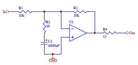
This has overall unity gain but a noise gain of 60 dB for AC, so with a given reference level you should be able to do the math on whether input voltage noise is in the right ballpark (should be about 0.56 mV, 20-20k, so roughly -66 dBFS for typical onboard audio or -71 dBFS for a 2 Vrms input). Plus, you could determine its small-signal bandwidth @ -3 dB when running a signal over it, which should be a tad over 20 kHz, reduced when adding a small capacitor (e.g. 22 or 47 pF) between pins 5 and 8. Since the circuit is so slow, decoupling should be quite non-critical. If needed, you can always make it even slower by swapping the 10ks for e.g. 22k.
There aren't an awful lot of good candidates for fakes - maybe LF356 at best, but in bulk the difference between those and TI NE5534Ps is pretty marginal already (maybe 6 cents each - 5534s are not expensive parts). Anyway, these are not using pin 8.
BTW, this circuit as shown should be good for an output noise level of around 2.6 µVrms, or a good 117 dB below 2 Vrms. I hope that's good enough for a TDA1541.
If you cannot hear the audio difference of a 4458 vs. 5532 in a line amplifier board, it is hard to carry a conversation with you. I can easily tell even though I am no golden ear. Filtering above 20KHz or ignore its poor waveform does not work because it affects the audio range by intermodulation. As several of you pointed out that the slew rate requirement is well established and there is NO NEED to reopen the discussion.
Thank you again for all the reply.
Last edited:
....how to verify either of these IC are genuine by checking how fast they are.....If you cannot hear the audio difference of a 4458 vs. 5532 in a line amplifier board, it is hard to carry a conversation with you.....
Slew rate testing: see attached lesson-plan. If your amp is faster than a '741
you might use 100kHz square wave. Since some commercial function generators use modest-speed buffers at output, simpler may be better. CMOS Schmitt RC oscillator is simple and fast. Add a 500 Ohm pot to set output level (you want to drive the opamp hard, but not slam it "many volts past the rails"). EDIT-- Mark already told you all this, even specific chip. Was he unclear?____________________________
> I claim I saw a UFO over my house last night.
You may not know Walt Jung. I don't like all he says, but he is more-right about the stuff he writes about than anybody else. His slew-rate articles in AA were debated at length for months, and I came away with the idea that he set an upper-bound on how fast we need.
http://hifisonix.com/wordpress/wp-content/uploads/2018/03/SID_and_TIM_W_Jung_77-79.pdf
Which is indeed all about the signal voltage. A system scaled for a 3V supply does not need the slew of a 30V system. (The problem with the old 4558 mixers is they "would" pass 7V signals, but cymbals above the rated 0.3V level just soiled the rug, and those users were clueless.)
Yes, not THD but IM, which is "worse" because it does not pitch-fit the music but is a random-pitch haze. Low-order IM of course drives Rock, but many-tone IM is just a dirty/smudged window.
Attachments
Last edited:
The LME49710 slews at 20V/microsec, quite a bit faster than 741. Mark did gave me all I need to know. I am too lazy to build the test rack and tried to see if there is an easier way.Slew rate testing: see attached lesson-plan. If your amp is faster than a '741
I was a charter subscriber of AA and is familiar with Walter Jung's early work on Audio Op Amp. When he pushed hard for the LM318's 70V/us slew rate as the top audio op amp, he did the audio community a disservice by forgetting the poor settling time spec of the chip. In later writing such as the 2005 Op Amp Application Handbook that Walter edited for Analogue Devices, the LM318 is not mentioned anymore. The AD797 was crowned the king of Audio Op Amp. AD797 has less than 1/3 of the slew rate of LM318, but superior settling time spec and excellent noise density too.You may not know Walt Jung. I don't like all he says, but he is more-right about the stuff he writes about than anybody else. His slew-rate articles in AA were debated at length for months, and I came away with the idea that he set an upper-bound on how fast we need.
http://hifisonix.com/wordpress/wp-content/uploads/2018/03/SID_and_TIM_W_Jung_77-79.pdf
Which is indeed all about the signal voltage. A system scaled for a 3V supply does not need the slew of a 30V system. (The problem with the old 4558 mixers is they "would" pass 7V signals, but cymbals above the rated 0.3V level just soiled the rug, and those users were clueless.)
Yes, not THD but IM, which is "worse" because it does not pitch-fit the music but is a random-pitch haze. Low-order IM of course drives Rock, but many-tone IM is just a dirty/smudged window.
The LME49710 has the same slew rate as the AD797, but a slightly higher noise density. I expect it to be an improvement over the NE5534.
Last edited:
It is ok for a low fi application such as boasting an cell phone output.What about this one: The Single NPN Transistor Audio Preamp | HACK A WEEK
It is ok for a low fi application such as boasting an cell phone output.
Soooooooooooooooooo inexperienced;-?
More like a little electret mic capsule perhaps, though R1 seems a bit high (probably 2.2k-6.8k depending on supply would be a better choice). Even then, the operating point of this circuit is not conducive to low distortion. Not to mention gain that depends on source impedance (it being an inverting amplifier of near-zero input impedance) and high output impedance, or relying on a quiet supply voltage for low noise. It's very, very basic.It is ok for a low fi application such as boasting an cell phone output.
You might still encounter this circuit as an IF amplifier. Better performance can be achieved even with a single transistor if you are willing to add a few more passives. Generally you'd find at least 2 transistors though, perhaps 3 - I mean in the 1970s / early '80s, when discrete circuitry was still common. You can get pretty decent performance then.
I probably wouldn't be going all-discrete these days. Not when you can, say, use an NE5534A with common-mode bootstrapping.
Last edited:
I agree with what you said. The last time that I came across such a single transistor amplifier was the output buffer in my Dynaco FM-5 tuner. The FM-5 buffer was biased for low distortion and did not have the low blocking capacitance of the input/output as in Marcel27's schematic. Marcel27's looks like an example for high school students to build to learn electronics. The topology is basic, but the design is not optimized. It is Marcel27's first and only post.More like a little electret mic capsule perhaps, though R1 seems a bit high (probably 2.2k-6.8k depending on supply would be a better choice). Even then, the operating point of this circuit is not conducive to low distortion. Not to mention gain that depends on source impedance (it being an inverting amplifier of near-zero input impedance) and high output impedance, or relying on a quiet supply voltage for low noise. It's very, very basic.
You might still encounter this circuit as an IF amplifier. Better performance can be achieved even with a single transistor if you are willing to add a few more passives. Generally you'd find at least 2 transistors though, perhaps 3 - I mean in the 1970s / early '80s, when discrete circuitry was still common. You can get pretty decent performance then.
I probably wouldn't be going all-discrete these days. Not when you can, say, use an NE5534A with common-mode bootstrapping.
Last edited:
Interestingly enough, because of the exponential transfer function of a BJT, THD is essentially independent of operating point, and depends only on the amplitude of the signal appearing across base and emitter....the operating point of this circuit is not conducive to low distortion.
IIRC, THD for a BJT common-emitter amplifier is around 2% for a 1mV (peak) input signal, regardless of operating point, and goes up rapidly as the signal amplitude increases. So there is actually no such thing as an operating point conducive to low distortion for a single BJT common-emitter stage!
(As long as the output is kept away from clipping, of course. In practice, biasing for adequate output headroom is more important than trying to bias for lower distortion.)
This characteristic (distortion % independent of operating point) holds true as long as the Ic/Vbe characteristic remains exponential. In practice, that holds true over a very wide current range - some four or five orders of magnitude, until the current gets big enough for bulk and ohmic resistances in the device to begin to dominate.
But the amazing thing about transistor amps is that BJT-based audio amps are a wonderful example of making a silk purse out of a sow's ear. The device itself has tons of harmonic distortion - but it also has such high transconductance that engineers came up with relatively simple circuits with extremely high voltage gain, allowing lots of negative feedback, which cleans up the distortion so much that the end result is far lower distortion than you could ever get out of a much more linear vacuum triode.
Now we can go buy a cheap op-amp with a gain of 100,000 - 1000,000 for pennies, apply feedback around it, and end up with distortion thousands of times lower than the ability of the human ear to hear it. Essentially perfect amps, for pennies. Amazing!
Sadly, available open-loop voltage gain for the simple common-emitter amplifier posted to this thread (in the Hack-A-Week link) is defined by the DC voltage across the collector resistor, at about 35 * (voltage across Rc). The circuit shown, run on 3 VDC, will have an open-loop voltage gain of barely about 50 times.
On the plus side, this is about as much gain as you can get out of a 12AX7 vacuum triode with a 300 V DC power supply! On the minus side, this isn't enough voltage gain to apply much negative feedback, and so the Achilles heel of the bipolar junction transistor - its high nonlinearity - is exposed.
-Gnobuddy
- Home
- Source & Line
- Analog Line Level
- Transistor Preamp