You have a plan, go with it, simplify the DC blocking.It's going to drive the JFET input of my DAO head amp which has high impedance. Can be whatever I set resistor to. Say 100k or 47k etc. So your suggestion of 1uF film is good. I have 1uF 230v MKT installed already. If I set 100k load to be driven. Although Juma set the values on schematic which had 220k load already. I can remove 100nF X7R and 10uF MLCC. On input I can remove 100nF X7R and 22nF film and replace with single 100nF 63v film.
R9 post321 is only there to dissipate leakage through the DC blocker when the output is disconnected. It can be just about any value. I generally use 2M2.
This is bypassed by the input impedance of the next stage when the interconnect is connected.
i.e. Zin = 100k becomes parallleled to this 2M2 to give a net load of 95k and still suits a 1uF blocking cap.
Last edited:
Don't. You'll be stealing too much headroom/swing capability.... running lower voltage rail, say 20v...
But last night I threw together a Pass B1 buffer preamp for the first time.
Mr Pass has updated the circuit:
http://www.diyaudio.com/forums/pass-labs/295398-choosing-best-output-coupling-capacitors-b1-2.html
This thread is a veritable treasure trove of preamp circuits. Two thumbs up!
Last edited:
Juma BF862 preamp works!
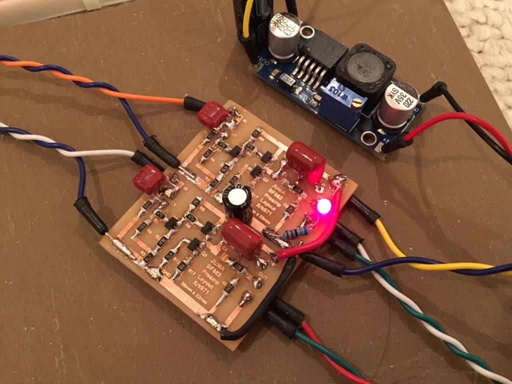
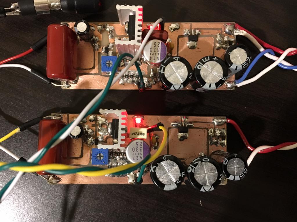
I replaced R2 with a 47R (tried 22R, 33R but not enough). Voltage across R3 is now 2.87v, voltage across R7 is 194mV and voltage at D of Q2 is 13.6v. I tested it and it sounds real nice, with the perfect amount of gain using a 270R for R3. So I built up the second channel. I am using a single 100nF 100v MKT (CBB) film cap on the input and a 1uF 230v MKT (CBB) film cap on the output. Input impedance of my amp is 100k.
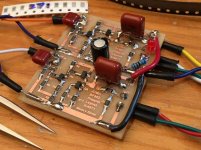
Here is a closeup of the preamp all built up:

Here it is with the temporary switching voltage booster to get 24v. I ordered a new 100VA trafo that will give me 28vdc and then I will use a Juma Easy Peasy Cap Mx to get down to smooth ripple free 24v rails for the amp and the preamp. Right now there is about 5mV ripple but I can't hear it as the amp PSRR is quite good.
The preamp now allows my new DT880-250 phones to really be driven at the perfect level because at 85% volume, I am starting to think it is too loud and measurements with DVM show about 1.6v AC (or 10mW into these 96dB/mW sensitive phones). So that is about 105dB apparent SPL in my ears.
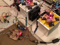
Here is the preamp actually playing music with the DAO amp:

So wondering if I should try a 470R shunt resistor?
This preamp/amp combo is very neutral. Just the right amount of bass and all is very balanced. The articulation is very impressive and I am really enjoying the sound.
Thanks to Juma for another great amp (or preamp in this case). The layout I posted works if anyone else wants to have a try. This is a fantastic sounding single ended class A preamp. So actually the same flavor as the power amp so it preserves the sonic characteristics of the main power amp.
I replaced R2 with a 47R (tried 22R, 33R but not enough). Voltage across R3 is now 2.87v, voltage across R7 is 194mV and voltage at D of Q2 is 13.6v. I tested it and it sounds real nice, with the perfect amount of gain using a 270R for R3. So I built up the second channel. I am using a single 100nF 100v MKT (CBB) film cap on the input and a 1uF 230v MKT (CBB) film cap on the output. Input impedance of my amp is 100k.
Here is a closeup of the preamp all built up:
Here it is with the temporary switching voltage booster to get 24v. I ordered a new 100VA trafo that will give me 28vdc and then I will use a Juma Easy Peasy Cap Mx to get down to smooth ripple free 24v rails for the amp and the preamp. Right now there is about 5mV ripple but I can't hear it as the amp PSRR is quite good.
The preamp now allows my new DT880-250 phones to really be driven at the perfect level because at 85% volume, I am starting to think it is too loud and measurements with DVM show about 1.6v AC (or 10mW into these 96dB/mW sensitive phones). So that is about 105dB apparent SPL in my ears.
Here is the preamp actually playing music with the DAO amp:
So wondering if I should try a 470R shunt resistor?
This preamp/amp combo is very neutral. Just the right amount of bass and all is very balanced. The articulation is very impressive and I am really enjoying the sound.
Thanks to Juma for another great amp (or preamp in this case). The layout I posted works if anyone else wants to have a try. This is a fantastic sounding single ended class A preamp. So actually the same flavor as the power amp so it preserves the sonic characteristics of the main power amp.
Attachments

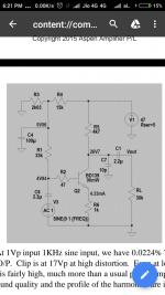
This thing needs a very clean supply and either an input or output attenuator (or an amp with one), otherwise the main thing it'll add is noise and hum. (Adding a gain of ~4.7 to the signal chain is going to magnify preamp noise accordingly.) Maybe that's the point, I don't know. Whether its effect is audible at all will depend on what kind of levels you are running it at, ~-74 dB of dominant 2nd at 0.7 Vrms, 1 kHz is not that much either.
This is a circuit given by Hugh Dean, in his AKSA story...It uses a single BD139 to derive Valve like sonics,that can be added to any power amp. Anybody here has attempted it?
More details on this circuit? can you post the link of this circuit?
All simple single rail SE Class A preamps need clean power. But that’s easy. A 12v Class 2 wallwart, feed a DC-DC step up or down, followed by cap Mx, the CRCRC. This gets me battery like low noise hum-free performance.
Sometimes just a Class 2 wall wart and cap Mx are enough for -100dB 50/60Hz hum level. Which sounds fine as below audible.
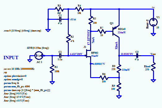
Here is another Hugh Dean Preamp is headphone amp with JFET driving a BD140. This one sounds excellent.
MOSFET Source Follower Headamp
A little hand etched prototype with on board cap Mx:
Sometimes just a Class 2 wall wart and cap Mx are enough for -100dB 50/60Hz hum level. Which sounds fine as below audible.
Here is another Hugh Dean Preamp is headphone amp with JFET driving a BD140. This one sounds excellent.
MOSFET Source Follower Headamp
A little hand etched prototype with on board cap Mx:
Last edited:
Much of the thread has been kinda sorta hilarious, but not in a good way when I think about the underlying causes.Hilarious ...
To heavily paraphrase Winston Churchill, "Never have so many used so much silicon to such little effect."

-Gnobuddy
Here's one I came up with several years ago. I make no claims regarding originality or elegance. Simulation says this one should do 10 Vrms at <0.01% THD10k (dominant 2nd by far). Do read the notes on design objectives and caveats.
Regular version:

Simple bootstrapped cascode input version with 4 whopping transistors:
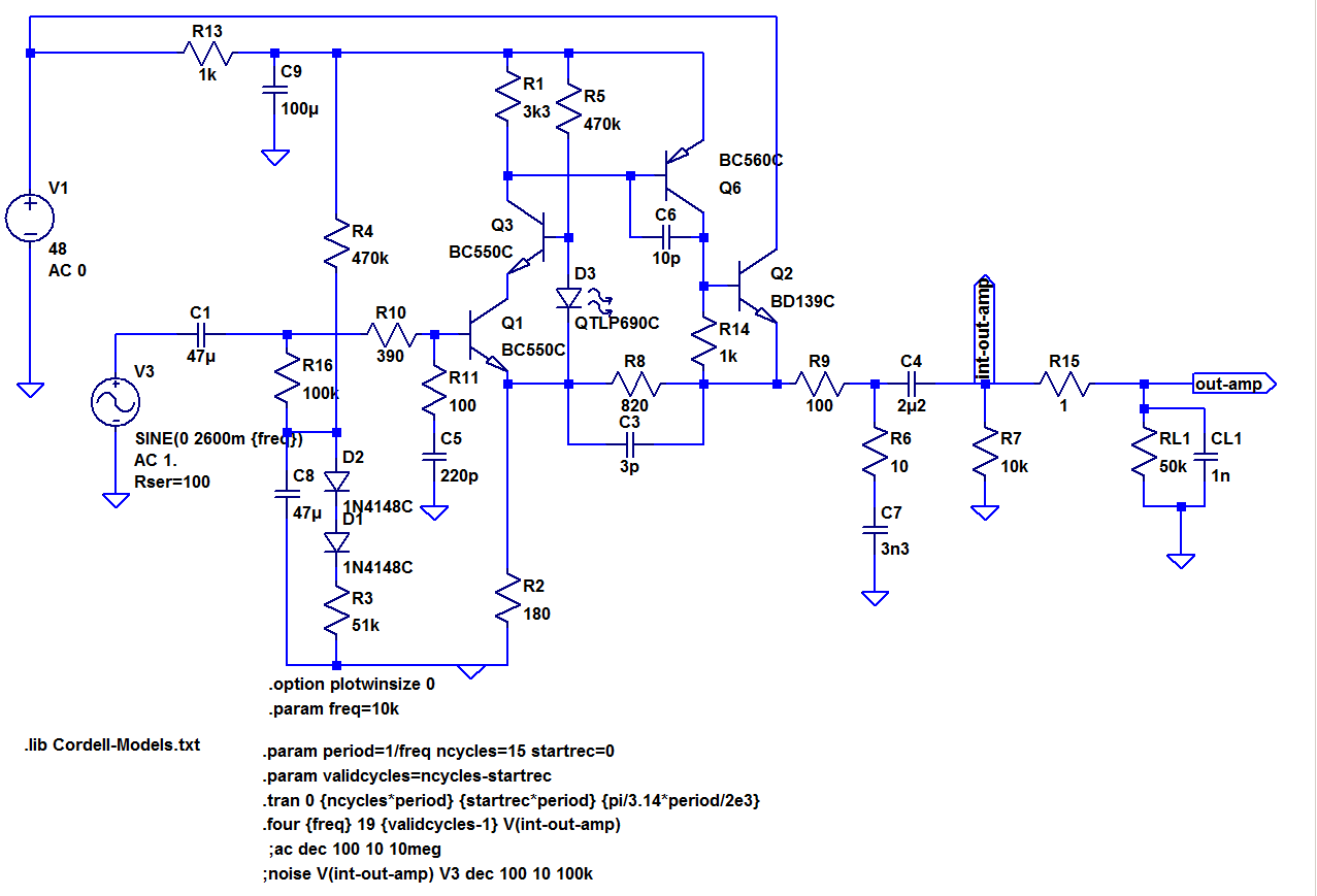
I tweaked this one a little after noticing a bit of a slew rate problem in the original design, it's closer to 0.002% now and stability appears unaffected, with current noise remaining uncritical. Maximum output is slightly higher, too (15 Vrms). As mentioned in the notes, PSRR for the cascode version tends to be a hint lower but still sims at >100 dB (70 Hz - 25 kHz) like this, with further tweakability up top when throwing a minimum of additional RC filtering at the 48V rail (e.g. 10R + 4µ7 || 100n). Your mileage (LEDs) may vary.
If someone would like to do a layout for this and try it out, be warned - this one's a little hottie and may be somewhat unforgiving in terms of ground and power routing. I never was entirely satisfied with power-on pop either.
Regular version:
Simple bootstrapped cascode input version with 4 whopping transistors:
I tweaked this one a little after noticing a bit of a slew rate problem in the original design, it's closer to 0.002% now and stability appears unaffected, with current noise remaining uncritical. Maximum output is slightly higher, too (15 Vrms). As mentioned in the notes, PSRR for the cascode version tends to be a hint lower but still sims at >100 dB (70 Hz - 25 kHz) like this, with further tweakability up top when throwing a minimum of additional RC filtering at the 48V rail (e.g. 10R + 4µ7 || 100n). Your mileage (LEDs) may vary.
If someone would like to do a layout for this and try it out, be warned - this one's a little hottie and may be somewhat unforgiving in terms of ground and power routing. I never was entirely satisfied with power-on pop either.
Attachments

Last edited:
Do you know what is the quad Opamp IC used in this kit?"Any good small, easy, high fidelity transistorised preamplifier circuit that i can build"
I agree, the title of the original thread is shown above.
Why not buy a simple kit from E/Bay as per shown below for $8
Musical Fidelit A1 Stereo Preamp Preamplifier Tone Board DIY Kits Dual Channel | eBay
Food for thought.
cheers
I decided on a JC-2 clone. The schematic is pretty faithful to John Curl's original. It may be an older design, but the topology is still very good sonically. The simplicity of the circuit allow builder easy matching of components. The PCB provides a neat looking finished product.
The volume control and input selection are relay based linear step ladder volume with remote also from e/bay. Waiting for delivery. Will report how good or how bad it sounds in a few months.
Last edited:
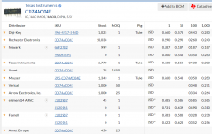
Do you know what is the quad Opamp IC used in this kit?
TL084CN from the ebay kit image.
Last edited:
TL084CN from the ebay kit image.
Thank you for the sharp eyes.
There are many good opamp preamp board on e-bay. My favorite is this one.
NE5532 Preamp HiFi Pre-amplifier Assembled Board (With servo power supply) 978078957192 | eBay A board using dual opamp is easier to upgrade. I also like the servo controlled power supply onboard which assures low noise in the audio band.
The TL-084CN is perfectly fine for many application. The PSRR of the TL-074/-84 series is not very good. A good rectifier/regulator board is highly recommended for the Musical Fidelity A1 clone board which can make it sound very good.
Last edited:
After I received the items, I set aside the JC-2 board and used remote controlled selector and volume control alone for several week, essentially as a passive preamp. It is one of the best e/bay value that I got in recent years. It is completely quiet and perfectly neutral as it should. No switch noise that I can hear. I have 3 inputs connected. The Harman Kardon AP2500 used as a phono stage only, a Marantz ST7001 tuner and a modified ES9038Q2M DAC for cable TV box and Blu Ray player (also for streaming). The preamp output is routed to a cabinet housing the 3-way Linkwitz-Riley Crossover and the 3 stereo power amplifiers.I decided on a JC-2 clone. The schematic is pretty faithful to John Curl's original. It may be an older design, but the topology is still very good sonically. The simplicity of the circuit allow builder easy matching of components. The PCB provides a neat looking finished product.
The volume control and input selection are relay based linear step ladder volume with remote also from e/bay. Waiting for delivery. Will report how good or how bad it sounds in a few months.
Because of the multiple connection and distance, I feel like adding a output buffer. The JC-2 board was one of the lowest cost all discrete option on e/bay.


After adding the JC-2 board, the sound remains neutral and musical. After 6 months, I have one complaint against this JC-2 board. It is very good 90% of the time. But if I listen to music with exceptional dynamic range and want to turn up the volume more, I can hear a faint noise in the background. The board is not extra noise, Just the combined result of a simple JC-2 with a simple power supply. The noise would not be noticed by most users.
I am waiting for the delivery of a 3-stage line amplifier which clones the SUGDEN SDA-1 DAC output board and a low noise power supply.
Assembled HiFi Preamplifier Preamp Refer SUGDEN SDA-1 DAC For Amplifier Class A | eBay
AC-DC LM317 LM337 LF353 Servo Rectifier Filter Power Supply Module Adjustable M 783710088352 | eBay

The NE5534 is adequate for this board. But I will try LT1115 or LME49710 to see if I can hear any different in noise and other audio performance. The use of a DC servo instead of large output capacitor should be a plus in both sound and cost.
Last edited:
I just ordered a bunch of LME49710 from Neoelec in NIAGARA FALLS, NY. How reputable are they as an electronic supplier? They told me that their LME49710 were from TI directly and are leftover from an old project.
What is the best way to test slew rate of these LME49710? Or the easiest way. I have a 100KHz signal generator (Heathkit IG-18) and an Owon 100MHz oscilloscope.
I got my LME49720 from DigiKey, but I cannot find any established distributor who has the LME49710.
What is the best way to test slew rate of these LME49710? Or the easiest way. I have a 100KHz signal generator (Heathkit IG-18) and an Owon 100MHz oscilloscope.
I got my LME49720 from DigiKey, but I cannot find any established distributor who has the LME49710.
The best way to test slew rate is to apply a square wave input with very fast risetimes and very fast falltimes. Unfortunately, a 100 kHz function generator is unlikely to give sufficiently fast edges.
If you use very short wires and lots of supply bypass capacitors, you can get 5 nanosecond risetimes and falltimes out of a 74AC04 logic inverter, even on a solderless breadboard. Since the AC family of digital logic gates has a 5 volt logic swing, that's 5 volts in 5 nanoseconds. Namely: 1000 volts per microsecond slew rate. Plenty fast enough to test opamp slew rate.
Build a little 1 kHz oscillator out of a 555 timer chip, buffer its output through a 74AC04, and apply those blazing speed edges to your amplifier through an AC coupling capacitor. Presto: the amplifier slews like the dickens.
_
Attachments
Last edited:
- Home
- Source & Line
- Analog Line Level
- Transistor Preamp