Hello,
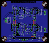
i'm trying to route a pcb (24db/octave 2 way active crossover) that I plan to etch using the toner transfer technique.
It will be single layer pcb, the top layer traces will be implemented by wires.
I would like know if the rooting is optimal in terms of noise distortion etc.
Does somebody has some advices to optimize the layout?
Thanks in advance,
Nicolas
Attachments
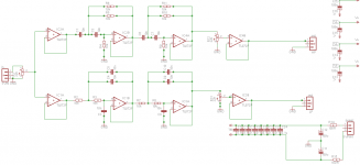
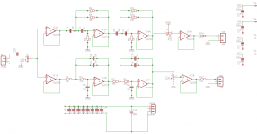
Schematic
hello,
Here is the schematic, it's a classical LR sallen key fourth order 2 way crossover with a corner frequence @ 1.6kHz that I plan to use with a 10 inch woofer + B&C DE250 horn loaded compression tweeter.
There is no delay correction included in the crossover since I plan to physically align acoustic centers of the 2 speakers.
The crossover outputs will feed LM3886 based amplifier modules.
for the components:
opa2134 for the operational amplifiers
wima FKP2 series for the capacitors
ceramic capacitors for decoupling(under the opamps)
low esr electrolytics for decoupling next to the opamps.
I'm afraid that the ground plane in post #1 will pick up noise...
any advice is welcome...
BTW: has anybody experience with discrete state variable filters? see TI uaf42?
Attachments
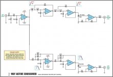
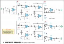
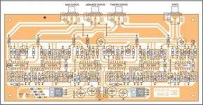
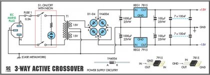
I use this one which is identical to yours, it's a three way but I only use it for two way.
Maybe you can get some ideas from it. It's also single sided. No noise/hum very good.
Cheers George
Maybe you can get some ideas from it. It's also single sided. No noise/hum very good.
Cheers George
Attachments
Thanks George!
Will put inputs and outputs on the same side of the board. It makes more sense in term of interfacing with other circuits.
Will add the output resistors for short circuit protection and add DC blocking caps on the inputs.
Will stick on the 2 way design since combining two 2 way boards, you get a 3 way crossover.
Do you think that separating PSU GND and signal GND will bring a substantial benefit?
Many of your traces are on the same side as the planes. This resuts in a plane that has been "cut" many times.
You will need a signal return plane on the top side with no cuts or as few cuts as you can manage. That allows the return signal currents to take the lowest impedance route back to the source. You DON'T want signals passing across cuts and having to take another route to get back to the source.
You may have to make those 4 top side connections by wires flying over the plane if some return signal needs to cross any of those paths.
I don't think you can make an effective signal return plane and a power return plane on a 2sided PCB. If I read H.Ott correctly even 4 planes falls short, he suggests 6 planes or more.
With 4, or more, dual opamps there are too many traces crossing to and fro to combine dual polarity power and all the signal returns into one plane. but maybe a Member can guide you to a good compromise.
How many are you building? If just one, for you, consider just using perf board, and doing point-to-point wiring. Years ago, I successfully build a 3-way stereo crossover using quad op-amps that way. No consideration of ground-plane or other routing, just wires. Worked great for 20 years before I retired it in favor of DSP. Finish the project in a couple days.

Low signal why not use SMD and shrink the design down.
The layout in 4 has plenty of antenna structures on it, designed for cheapness not signal integrity.I'm with Andrew here, low level signal use a solid ground plane and provide the best environment for signal integrity...
The layout in 4 has plenty of antenna structures on it, designed for cheapness not signal integrity.I'm with Andrew here, low level signal use a solid ground plane and provide the best environment for signal integrity...
Use metal film usually referred to as "thin film"
Select a size that gives a power rating well above worst case operational power.
805 package is usually around 100mW to 125mW.
That would indicate a normal maximum operational power of around 50mW. For a feedback circuit use less than 10% of the max rating. Lot's in series is far better than using a big one and better than using many in parallel.
found these SMD:
Vishay Dale Thin Film : Very low noise and voltage coefficient (< -30 dB)
0,815 € each
http://www.mouser.be/ProductDetail/...=sGAEpiMZZMu61qfTUdNhGwisekDOKsiwae60JVnN1fI=
Would these be good candidates?
Vishay Dale Thin Film : Very low noise and voltage coefficient (< -30 dB)
0,815 € each
http://www.mouser.be/ProductDetail/...=sGAEpiMZZMu61qfTUdNhGwisekDOKsiwae60JVnN1fI=
Would these be good candidates?
Yes but what kind of SMD resistors to use for audiophile purposes?
Thin film
http://www.mouser.fr/Passive-Components/Resistors/Film-Resistors/Thin-Film-Resistors-SMD/_/N-7gz44
I highly recommend you to read this document from texas instrument.
All you want to know is here :
http://www.ti.com/sc/docs/apps/msp/journal/aug2000/aug_09.pdf
All you want to know is here :
http://www.ti.com/sc/docs/apps/msp/journal/aug2000/aug_09.pdf
A good but old paper. The first part regarding PCB materials should mention the IPC and the section regarding 45 and 90 degree traces is out of date and incorrect unless you are working at microwave frequencies.
As to audiophile requirements, I do sensitive analogue/digital boards (last on 10 layers, 2000 components) where requirements for accuracy are quite serious and easily available parts are as recent posts have shown readily available... For this sort of use and as Andrew T has pointed out de-rate the components, we add attributes to each resistor in a design for actual voltage across the device, then feed the figures into a spread sheet (with the other resistor attributes) and don't run any resistor greater than 50% of rated power. In most circuits you will find you are running pretty low anyway. As well as helping accuracy a 50% de-rating is required for MTBF figures. There are good commercial components, an audiophile component is usually either a overpriced standard product or silly things such as exotic capacitors. A search for low noise SMD resistors will provide plenty of options.....
As to audiophile requirements, I do sensitive analogue/digital boards (last on 10 layers, 2000 components) where requirements for accuracy are quite serious and easily available parts are as recent posts have shown readily available... For this sort of use and as Andrew T has pointed out de-rate the components, we add attributes to each resistor in a design for actual voltage across the device, then feed the figures into a spread sheet (with the other resistor attributes) and don't run any resistor greater than 50% of rated power. In most circuits you will find you are running pretty low anyway. As well as helping accuracy a 50% de-rating is required for MTBF figures. There are good commercial components, an audiophile component is usually either a overpriced standard product or silly things such as exotic capacitors. A search for low noise SMD resistors will provide plenty of options.....
A good but old paper. The first part regarding PCB materials should mention the IPC and the section regarding 45 and 90 degree traces is out of date and incorrect unless you are working at microwave frequencies.
As to audiophile requirements, I do sensitive analogue/digital boards (last on 10 layers, 2000 components) where requirements for accuracy are quite serious and easily available parts are as recent posts have shown readily available... For this sort of use and as Andrew T has pointed out de-rate the components, we add attributes to each resistor in a design for actual voltage across the device, then feed the figures into a spread sheet (with the other resistor attributes) and don't run any resistor greater than 50% of rated power. In most circuits you will find you are running pretty low anyway. As well as helping accuracy a 50% de-rating is required for MTBF figures. There are good commercial components, an audiophile component is usually either a overpriced standard product or silly things such as exotic capacitors. A search for low noise SMD resistors will provide plenty of options.....
Experience can't be beaten

I'm still thinking that the johnson noise of modern resistors is inaudible if you don't exceed reasonnable values with simple BF desings.
... i use standard thick film resistors.
Metal film, or wire, or foil, has Johnston noise (or was he Johnson?)
The other noises are quite low.
Metal oxide as a slightly higher level of these other noises, but Johnston noise is the same.
But noise from the resistor is typically not an issue for line level (or above) stages.
However tempco and voltco may be a bigger effect. Metal oxide is usually much worse than metal.
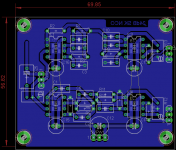
board updated
hello,
updated the board and schematic of post #1 :
About compacting the circuit by using SMD components, one question puzzles me:
Is it best to keep trough hole components and use polypropylene caps (low distortion caps)
or
Is it best to have a super compact circuit by using smd component but without polypropylene caps (I do not find smd polyropylene caps of 10nF)
What kind of SMD caps to use?
hello,
updated the board and schematic of post #1 :
- minimized the loop area by rotating r4 & r9 in the bottom HP section
- removed psu connection to signal ground connection
- added attenuator on each output
- added an input decoupling cap
About compacting the circuit by using SMD components, one question puzzles me:
Is it best to keep trough hole components and use polypropylene caps (low distortion caps)
or
Is it best to have a super compact circuit by using smd component but without polypropylene caps (I do not find smd polyropylene caps of 10nF)
What kind of SMD caps to use?
Attachments
Last edited:
D.Self did some work on measuring the distortion of active filters.
He found that ONE particular capacitor did introduce distortion when an MKT was used. He measured an MKP in that location and the distortion was gone. He found that the other locations could use MKT, or MKP and he found no added distortion.
You would need to read his paper/book to find which needs a low distortion capacitor.
You can use a dip socket to mount the frequency setting capacitors.
This allows you to plug in alternative turnover frequencies after the build is complete. Suits 0.3" caps in a dip header, although 0.2" and 0.4" can just about be squeezed in.
The resistors could all be smd if that suits you. You can get NPO/COG in multilayer smd but they tend to be lower values.
I agree with most of what Andrew says
And indeed he has taught me many a lesson when I have been attempting a similar layout task.
I have tried the DIL socket trick and find it particularly useful for proto circuits and strip board.
However, I found SIL sockets more useful on a PCB as you have easier pitch options at the usual 0.1" increments.
In a S and K filter with several cascaded stages, I found that component tolerances come into play. In proto designs I used 5% Capacitors and 1% metal film resistors. It worked fairly well. In the final design I opted for 0.1 or 0.5% resistors such as E96 Welwyn RC55Y series ( for the low temp Co. And large range of values ) and 1% PP film Vishay capacitors, in order to minimise the effect of component tolerances.
Whether you NEED to do this is a matter of opinion (or how anal you are about these things, filter Q etc.)
I hope I have added something to the usual sterling advice.
Last edited:
- Status
- This old topic is closed. If you want to reopen this topic, contact a moderator using the "Report Post" button.
- Home
- Source & Line
- Analog Line Level
- Need advise about active crossover routing