Here my schematic for Pro Audio Amplifier Limiter.
The idea is using P-JFET with biased continuously to perform continues attenuation in the linear area, to perform like class A amplification but in opposite function as attenuation. As it is attenuated then it produce small signal voltage then it is amplified. The result looked like very good, fast and linear.
Comment and suggestion is welcomed.
Attachments
Translate the instruction on the circuit:
Function:
This circuit provide three at once functions: Limiter, Balanced Input and Gain Control.
1. Limiter prevents amplifier clipping with any input high input
2. Balanced input amplifier to be unbalanced XLR
3. Gain Control, add input sensitivity to match the input voltage with amplifier gain
4. The circuit can be used as inverting phase and for kit BTL
Install:
This circuit is to be installed on the input amplifier. Volume pot is already included in the circuit.
Input = XLR + Hot, -Cold, GND or if unbalanced input use + Hot, GND and -Cold connected to GND.
Output = XLR + Hot, -Cold, GND or if unbalanced output use + Hot, GND and –Cold not used.
The circuit can also be used for BTL or inverting because the output is + and – phase.
Setting:
This circuit has Gain Control to match with amplified gain. After the amplifier installed and connect amplifier with speaker or dummy load at nominal load. Then turn the gain in the minimum position and put 2V input so the limiter will work (LED Limiter active will ON). Then turn rise the gain control until output amplifier gain is start to clip. Then reduce in order to free clip. The gain position is marked as 100% output of amplifier. Amplifier hence will be free from clip.
Limiter can also be used to limit the power amplifier if using smaller speaker than nominal output of amplifier. As above, the 100% output has been marked at the gain control position hence by reducing the gain control less than 100% position will limit the amplifier output.
So the speaker will be safe.
Kartin, have you done any distortion measurements versus attenuation setting?
Jan
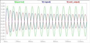
I did the spice simu. It shows about -40dB k2 across the JFET drain-source with the signals as shown in the original asc-file.
Last edited:
I built limiters using much the same circuit back in the 1980s, but your circuit is missing:
1. Full wave rectification. Just replace the diode with another transistor, common base. Add an EF if you want to balance the two phases.
2. Optimize the FET linearity by adding 1/2 the audio voltage to the gate voltage. This is available by splitting the lower resistor in the op-amp feedback.
The attach time can be faster than the first 1/2 cycle of audio but that may not be the desired result.
Last edited:
Has this been fixed? and can it be applied in class h?Final Version
Tested by Andrew Lebon. It is working
- Status
- This old topic is closed. If you want to reopen this topic, contact a moderator using the "Report Post" button.
- Home
- Source & Line
- Analog Line Level
- Audio Limiter with JFET Class-A