Hello DIYers...
I have recently come across two NYAL Super IT phono preamps. Both are in pretty rough shape, a little rigging, and no power supplies.
I would like to restore them both to as new...
Does anyone here have a schematic they would share, or have any technical info they can offer? Can't find much on the web about it.
Thanks
Caleb
Super IT Schematic?
There have been posts and threads for years with people asking for a schematic for the NYAL Moscode Super It, and it seems like NOBODY has this. George Kaye and Moscode seem to no longer exist, or so it seems. So, does anyone out there have it? It seems amazing that it can't be found anywhere on the internet. Mine keeps blowing one of the big power supply electrolytics, and I know others have had this problem as well. A schematic sure would be nice... Anyone? Thanks, JV
There have been posts and threads for years with people asking for a schematic for the NYAL Moscode Super It, and it seems like NOBODY has this. George Kaye and Moscode seem to no longer exist, or so it seems. So, does anyone out there have it? It seems amazing that it can't be found anywhere on the internet. Mine keeps blowing one of the big power supply electrolytics, and I know others have had this problem as well. A schematic sure would be nice... Anyone? Thanks, JV
http://www.moscode.com/george_kaye_moscode.htmThere have been posts and threads for years with people asking for a schematic for the NYAL Moscode Super It, and it seems like NOBODY has this. George Kaye and Moscode seem to no longer exist, or so it seems. So, does anyone out there have it? It seems amazing that it can't be found anywhere on the internet. Mine keeps blowing one of the big power supply electrolytics, and I know others have had this problem as well. A schematic sure would be nice... Anyone? Thanks, JV
http://kayeaudiolabs.com/
Super it Fuses
I lent my Super It to a neighbor years ago. After it was returned I put it away.
Now it doesn't work. I see that the fuse by the filter caps is missing. Maybe it blew and he never said. In any case I was wondering if you knew the value of that second fuse? ..and, no, I don't have a schematic. Darn!
Gypsysailor
now , I have a question too :
what's the value of R2 ? i have 10 turn 5K multiturn pots instead of a fixed metal film resistor .
TIA
Bias Adj
Bias Adj
I know , but what fixed resistor value should be there , instead of the non Original multiturn pot installed on my PCB ?
TIA
I know , but what fixed resistor value should be there , instead of the non Original multiturn pot installed on my PCB ?
TIA
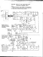
I've been working on my Super It in the last month. I use the voltage drop across the plate resistor (R5) to properly set the source resistance of the input FET. The proper bias point gives you 1mA through R5 and a voltage drop of 100v since R5 = 100K.
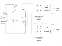
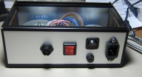
I recently built an external power supply for my unit, since the external transformer seems to have blown an internal fuse. Here's a schematic showing what I built.
Attachments
I've been working on my Super It in the last month. I use the voltage drop across the plate resistor (R5) to properly set the source resistance of the input FET. The proper bias point gives you 1mA through R5 and a voltage drop of 100v since R5 = 100K.
I recently built an external power supply for my unit, since the external transformer seems to have blown an internal fuse. Here's a schematic showing what I built.
neat PS box !
as for the R2 value , it looks as the 5K pot that is placed onto my board isn't a bad idea at all ? making things a lot easier to adjust the input stage bias . otherwise one would realy need a very close balanced and matching pair of input tubes 12AX7 , not an easy task to find .
Thanks for the info
Thanks. It's an 8" x 5" x 3" box (20.3cm x 12.7cm x 7.6cm) from MC Series Metal Cabinets - Wolgram Engineered Plastics, LLCneat PS box !
The current is actually independent of the 12AX7. It's determined by the input FET, which is never changed and is quite stable. So one just sets it once and it's good for the life of the unit.as for the R2 value , it looks as the 5K pot that is placed onto my board isn't a bad idea at all ? making things a lot easier to adjust the input stage bias . otherwise one would realy need a very close balanced and matching pair of input tubes 12AX7 , not an easy task to find .
Thanks for the info
Thanks. It's an 8" x 5" x 3" box (20.3cm x 12.7cm x 7.6cm) from MC Series Metal Cabinets - Wolgram Engineered Plastics, LLC
The current is actually independent of the 12AX7. It's determined by the input FET, which is never changed and is quite stable. So one just sets it once and it's good for the life of the unit.
Thanks Gary ,
I suppose than that NYAL didn't pay a lot attention to fet matching .. there's a significant difference between the voltage across R2 . 1,1 Volt vs 2,2 Volt.
I consider to change them for some modern Jfet parts at some point . who knows .
Thanks again
That's what I did in mine - I replaced the FETs with 2SK170 low noise FETs. Matching isn't too critical. There is another variable resistor in one channel of the 2nd FET/Tube stage - R11. One uses that to match the gain between the two channels. If you had well matched FETs then you could get rid of that variable resistor too.Thanks Gary ,
I suppose than that NYAL didn't pay a lot attention to fet matching .. there's a significant difference between the voltage across R2 . 1,1 Volt vs 2,2 Volt.
I consider to change them for some modern Jfet parts at some point . who knows .
Thanks again
One thing I notice is that the gain is really high with the 2SK170 FETs - almost 62dB total gain. If I were doing it again, I might only use the 2SK170 for the input FET and then use a lower transconductance FET for the 2nd stage.
Have you ever measured the gain of your Super It? If you put in a 2 or 3mv 1khz sine wave, what's the magnitude of the output?
That's what I did in mine - I replaced the FETs with 2SK170 low noise FETs. Matching isn't too critical. There is another variable resistor in one channel of the 2nd FET/Tube stage - R11. One uses that to match the gain between the two channels. If you had well matched FETs then you could get rid of that variable resistor too.
One thing I notice is that the gain is really high with the 2SK170 FETs - almost 62dB total gain. If I were doing it again, I might only use the 2SK170 for the input FET and then use a lower transconductance FET for the 2nd stage.
Have you ever measured the gain of your Super It? If you put in a 2 or 3mv 1khz sine wave, what's the magnitude of the output?
No , not yet but will do soon , comparing it to other side projects I am doing .. E280F / 2SK369 cascode stages , I estimate the gain of the Super-it in the 60+dB ballpark . just more noise . and for some reason I think that degeneration and decoupling of the lower fet is not my cup of tea .
I spend an enormous amount of time in channel selecting and matching parts on that side project , and it's truly worthwhile to do so I figure . but also the power supply arrangement proved to be a major part of the resulting sound .
THX
Hello:
I have another Super-it question. After waiting a month for a new filter cap (HV) that was obviously bad, As I installed it then saw that Q1 was fried also (hard to see with the old cap in the way). The information on Q! was burned off so I cannot tell what it was. Can one of you have a look and tell me?
Thanks,
Gypsysailor
- Home
- Source & Line
- Analog Line Level
- Moscode Super IT - schematics? power supply?