Noticing that on the Front panel from Carl it is showing XLR In then 4 lines in after. Anyone understand that. Was there a version with only 1 XLR?
The markings on the front panel that you have machined must be edited to the IO arrangement of your build. I have built several variations. What I sent you is just one of those variations. Changing the markings is very easy using the FREE Front Panel Express software that is downloadable from their site.
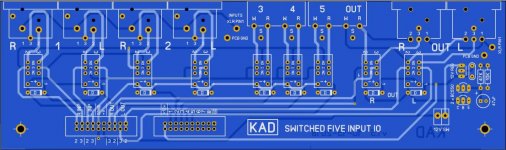
The standard IO PCB that I ship has two XLR balanced channels and 3 unbalanced channels in and looks like this ...
Attachments
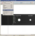
Yes I agree Carl and I am using the I/O board you have pictured. I have been trying to mod the fpd.file but whenever I click on anything on the front panel it highlights the whole panel detail as if it was dropped in as a pic or something. Trying to figure out how to modify individual labeling. If you know anything about this please let me know.
... I have been trying to mod the fpd.file but whenever I click on anything on the front panel it highlights the whole panel detail as if it was dropped in as a pic or something. Trying to figure out how to modify individual labeling. If you know anything about this please let me know.
You need to 'ungroup' the items that you are clicking on as shown in the attached PIC ...
Attachments
If you are using the layout I drew it was a Volex 17252 0 B1 https://canada.newark.com/volex/172...d|kwd-13704201947|&CMP=KNC-GCA-GEN-SKU-MDC-NF These are fairly generic so others should fit as well.
So I have made mods that I want to the panels with FPD. More questions though I'm assuming most have used DIY audio 1U enclosure. I'm also assuming sent those panels into FPD to be CNC'd. They can print the labeling onto a anodized panel correct?? If all of my assumptions aren't correct someone please inform. Also did people order the backplate with the IEC hole already included?
FN9260SB-2-06-30
If you use the fpd file, that is for 2A and for 3 mm rear panel thick. You will find it now @ Mouser
If you use the fpd file, that is for 2A and for 3 mm rear panel thick. You will find it now @ Mouser
This is the chassis I used for my pre-amplifier..
1pcs case 1 u case 19 inch case switch case Electric power communication industrial aluminum chassis server chassis-in Computer Cases & Towers from Computer & Office on AliExpress
Best Regards
Farooq
1pcs case 1 u case 19 inch case switch case Electric power communication industrial aluminum chassis server chassis-in Computer Cases & Towers from Computer & Office on AliExpress
Best Regards
Farooq
This is the chassis I used for my pre-amplifier..
1pcs case 1 u case 19 inch case switch case Electric power communication industrial aluminum chassis server chassis-in Computer Cases & Towers from Computer & Office on AliExpress
Best Regards
Farooq
Farooq,
The price certainly is right! How about the build quality and durability of the product?
Farooq,
The price certainly is right! How about the build quality and durability of the product?
The material is hard MS. Fixtures are countersunk type. Front is brushed aluminum. I found easy to cut hole using this...all sides are removeable. Feels quite strong when assembled. No flex. Also rubber feet. I have ordered two so far. Parts were well packed when shipped. No damage.
Best regards
Farooq
Attachments
Last edited:
BC560 BJT alternative?
Did a quick search through this thread and did not find an answer, so here goes.
Finally ordering up the parts for the pre-amp build and the BC560 BJT seems to have become extinct, i.e. discontinued by the manufacturer and no one has it in stock.
What is the recommended replacement PNP transistor. The only other low noise PNP from ON/Fairchild in the same package is the BC559 but the emitter and collector voltage is 15 to 20 volts less.
Any thoughts/suggestions?
TIA,
Bill
There are still many BC560s around. For example here: BC560 BC560B Low Noise Transistor PNP
BC860 is the surface mount equivalent. No one makes through-hole small signal transistors any more, they will all go, except the most popular legacy devices, so start thinking about breakout boards and modules. For instance a SOT23 device can be mounted on a fragment of protoboard with 3 header pins sticking down with a little ingenuity, and SOT223 packages can be directly soldered to a row of three header pins.
I think there's a gap in the market here for someone...
I think there's a gap in the market here for someone...
Can board sets still be purchased for this preamp? If not are gerbers available for members to still have them made?
You can still get a PCB kit. I just sent you a private message with the details.
... Grounded xlr pin1 to the chassis with short wires. Needed a tantalum cap on the I/O board to get 12V. ...
BK
Dear BK,
sorry to get this part of the thread back to life, I was in the same situation as you and Hicoco and followed the recommandations of Jan (R5/R6 at 100R and R9/R10 at 1K) as I wanted to get the preamp powered with 17V and as my main voltage is around 230-240V.
Everything is running smoothly although I find the heatsink a little bit hot (around 50°C).
May I ask what cap you used exactly and where you put it precisely and maybe why it helps getting 12V? (I currently measure 15V in this part of the I/O board )
Second question, hope I'm not disturbing too much, shall I definitely ground the pin 1 of the XLR to the chassis per your suggestion or is it something you prefer doing but not mandatory. No cap needed here? Just a short?
Last but not least, @Carl, MANY THANKS for all that stuff, you gave me the power of Doug and I really like what I ear.
Thanks all.
Raph
- Home
- Source & Line
- Analog Line Level
- Doug Self Preamp from Linear Audio #5