What value load resistors are you using?
I did 3 test with 3 different value of load resistors:
240R 3W, 2X 240R 3W parallel, 3x240R 3W parallel.
Do you get clean signals thru both preamp channels when connected to it?
Yes very clean signals...with my oscilloscope for 1Kz and 150mV input
and 200mA 17V+ and 154mA 17V- at the ammeter.
There might be a problem on the preamp board. You could have a bad or backward op amp or solder bridge.
I checked, and nothing suspect...
If you have 21.5V before the regulator, wanting 17V out of it, under load, the transformer is fine. 4V dropout is more than enough.
Excessive heat, what is that? With 4 V across the reg and 200mA load is 0.8W. Seems very little but depending on heatsink can easily raise device temp 30 or 40 degrees. That's HOT to the touch.
Jan
Excessive heat, what is that? With 4 V across the reg and 200mA load is 0.8W. Seems very little but depending on heatsink can easily raise device temp 30 or 40 degrees. That's HOT to the touch.
Jan
Jan,If you have 21.5V before the regulator, wanting 17V out of it, under load, the transformer is fine. 4V dropout is more than enough.
Excessive heat, what is that? With 4 V across the reg and 200mA load is 0.8W. Seems very little but depending on heatsink can easily raise device temp 30 or 40 degrees. That's HOT to the touch.
Jan
I got around 60 ℃..65 ℃.
I changed the SK 104-2 ( External Length - Metric 25.4mm) who is in the Carl's BOOM with a SK104-6 ( External Length - Metric 63.5mm) heatsinks and the temperature drops of 10℃ on each side. But now i am too hight for the 1U chassis i bought..This is why i am looking for an other option..
Now something that not right, I changed the Transfo for a 15Vac 25VA because 18Vac was too hight after rectifiers (+-30V with no load and 27.3V with load), i have 240Vac at the primary)
Now i have 18,5Vac after transfo and +-25v after rectifers with no load and +-21,8 V with load.
With no load i am able to adjust the output at +-17V or more.
With 200mA load at the positive rail and 154 mA at the negative rail the output drop from +-17V to +-15V and i am not able anymore to adjust the voltage at a value higher than 15 Vdc when i turn the adjustable Pot.
Carl, ok i will post pics today.Hmm ...
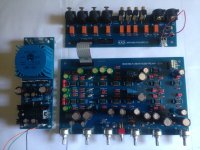
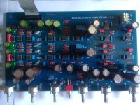
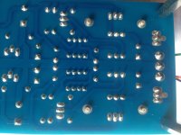
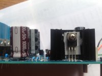
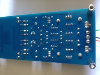
I invite you post a well lit hi-rez (as practical) top view photo of the power board for the group here to examine for you. Perhaps someone will be inspired with a fix.
Here they are:Hmm ...
I invite you post a well lit hi-rez (as practical) top view photo of the power board for the group here to examine for you. Perhaps someone will be inspired with a fix.
Attachments

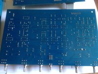
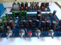
More from power board.....
Attachments
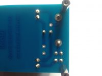
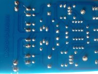
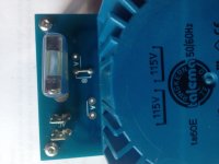
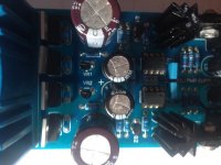
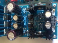
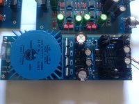
Hicoco, I can't tell form your pics - do you have the PS pcb version with jumpers to set line voltage? It also looks like traces of thermal compound in addition to silpads on the regulators. If you're using an insulated package you might eke out some additional thermal performance using just thermal compound and soldering the heatsink pins on the underside? Ensure all surfaces are clean and smooth. Datasheet shows max operating temp is 150C, so evidently a robust part. I'll let you know how mine behaves in a few days. As for your inability to increase output above 15V with load....
BK
edit - *now I see your newly added pics with jumpers*
BK
edit - *now I see your newly added pics with jumpers*
15 op amps. I love SS but this is overkill.
I used 2 tubes and 2 op amps to provide RIAA (turntable EQ) FM optimization and Bass/ Treble / Loudness EQ. Thats including the power supply at -130db ripple rejection.
Obviously appeals to different people for different reasons, or not. The very well-written 24pg LA#5 article offers insights and context...
BK
With no load i am able to adjust the output at +-17V or more.
With 200mA load at the positive rail and 154 mA at the negative rail the output drop from +-17V to +-15V and i am not able anymore to adjust the voltage at a value higher than 15 Vdc when i turn the adjustable Pot.
So what psu is that? Do you have a schematic you can post?
BTW SK129 is mechanically equivalent to SK104 as to PCB holes and TO220 holes, but is a bit wider. IF it fits the PCB it gives you a bit lower temperature.
Jan
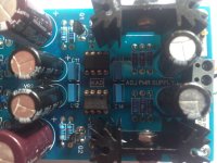
That is the PSU board that Carl sent with the Doug's PCB preampSo what psu is that? Do you have a schematic you can post?
BTW SK129 is mechanically equivalent to SK104 as to PCB holes and TO220 holes, but is a bit wider. IF it fits the PCB it gives you a bit lower temperature.
Jan
Attachments
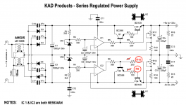
I think you are hitting the max output level of the NE5534. The opamp output must be about 1.2V above the supply output. With the opamp max output 2V below its own supply you are getting close to 15V + 1.2 + 2 = 18.2V needed input voltage.
R5 aggravates the issue due to several 100mV drop. You can try to change R5 to 50 ohms or so, and make R9 1k.
If you change the output voltage to 14V, does it work as expected? Or find an opamp with RR output.
Jan
Edit: I think there may be as much as 3V or more across R5, which makes the opamp supply needing to be more than 6V above the output.
That's one of the great advantages of the diyaudio Superreg, where the opamp is supplied from the output, needing less headroom (and better PSRR).
Last edited:
Yes i can drop the output under 15V, it work as expected,I think you are hitting the max output level of the NE5534. The opamp output must be about 1.2V above the supply output. With the opamp max output 2V below its own supply you are getting close to 15V + 1.2 + 2 = 18.2V needed input voltage.
R5 aggravates the issue due to several 100mV drop. You can try to change R5 to 50 ohms or so, and make R9 1k.
If you change the output voltage to 14V, does it work as expected? Or find an opamp with RR output.
Jan
I have more than 18,2V at the input..I have 21.8V with load..this is why i don't understand.. if i follow your math i should be able to get more than 17V at the output
Edit: just saw your edit..I will do the test for R5 and R9, Thanks Jan
Last edited:
Edit: just saw your edit..
I'm slow this morning, sorry .... ;-)
Jan
Yes i had 4,27v across R5..R5 aggravates the issue due to several 100mV drop. You can try to change R5 to 50 ohms or so, and make R9 1k.
Jan
Edit: I think there may be as much as 3V or more across R5, which makes the opamp supply needing to be more than 6V above the output.
That's one of the great advantages of the diyaudio Superreg, where the opamp is supplied from the output, needing less headroom (and better PSRR).
I did the test with R5 50R and R9 1k with 100R and 5kTrimmer Resistors with my breadboard and i am able now to adjust 17v output with load test resistors, i have 0,77V across R5, 17,4Vac secondary, +/-21V after rectifiers.
After 15 minutes with 60R load and 276 mA the BD139/140 was fine, no over heat. i will try longer with a final resistors in the board.
Do you thing i can use 47R instead of 50R.
Thanks again for your help Jan, i really appreciate.
Yes i had 4,27v across R5..
I did the test with R5 50R and R9 1k with 100R and 5kTrimmer Resistors with my breadboard and i am able now to adjust 17v output with load test resistors, i have 0,77V across R5, 17,4Vac secondary, +/-21V after rectifiers.
After 15 minutes with 60R load and 276 mA the BD139/140 was fine, no over heat. i will try longer with a final resistors in the board.
Do you thing i can use 47R instead of 50R.
Thanks again for your help Jan, i really appreciate.
Well done, yes use 47 ohms, or higher, up to 100 ohms should be OK. With 1.2V across the 1k, even 100 ohms only eats 0.12V from your overhead. 100 ohms may be better for stability.
Jan
Hicoco, glad you got it sorted out.
I just received my 15W power resistors and tested my PS with 100R on each rail.
No load = +/-17.0V set.
After 30min with 170mA load = +/-17.0V (no trimmer adjustment required).
Ambient = 31C
Diodes = 39C
Regulators = 49C at the bolt
All seems well with mine using the schematic values, 115V line input and 18V 7.5VA transformer.
BK
Great, what is the value after rectifiers ? and if you can across R5/R6 and R9/R10 ? ThanksHicoco, glad you got it sorted out.
I just received my 15W power resistors and tested my PS with 100R on each rail.
No load = +/-17.0V set.
After 30min with 170mA load = +/-17.0V (no trimmer adjustment required).
Ambient = 31C
Diodes = 39C
Regulators = 49C at the bolt
All seems well with mine using the schematic values, 115V line input and 18V 7.5VA transformer.
BK
Last edited:
Great, what is the value after rectifiers ? and if you can across R5/R6 and R9/R10 ? Thanks
24.5V after the rectifiers, 4.1V across R5/6, 1.4V across R9/10.
BK
- Home
- Source & Line
- Analog Line Level
- Doug Self Preamp from Linear Audio #5