Anyone have suitable replacement for xicon 140-50U5-473M-RC (47n Ceramic Capacitor 50V) from digikey or mouser? This is for the power supply.
I wasn't sure how to use their search engine to find a replacement and everything that came up was rather different.
On digikey the LM7915CTFS-ND is obsolete and the replacement MC7915CTGOS-ND and LM7815ACT-ND replacement is MC7815ACTGOS-ND.
I wasn't sure how to use their search engine to find a replacement and everything that came up was rather different.
On digikey the LM7915CTFS-ND is obsolete and the replacement MC7915CTGOS-ND and LM7815ACT-ND replacement is MC7815ACTGOS-ND.
Last edited:
look @ FG26C0G1H473JNT6 Mouser should workAnyone have suitable replacement for xicon 140-50U5-473M-RC (47n Ceramic Capacitor 50V) from digikey or mouser? This is for the power supply.
I wasn't sure how to use their search engine to find a replacement and everything that came up was rather different.
On digikey the LM7915CTFS-ND is obsolete and the replacement MC7915CTGOS-ND and LM7815ACT-ND replacement is MC7815ACTGOS-ND.
look @ FG26C0G1H473JNT6 Mouser should work
Thank you!
Project Updates: IO & Power Supply PCBs
Changes ...
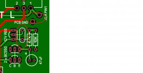
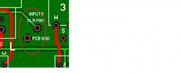
IO PCB: Per my previous commitment I have added a capacitor pad to output of the 12v regulator that powers the relays. I have also added support for alternate grounding schemes for the XLR connectors. As a builder you must now either add a wire jumper to the system ground or to the chassis as is pro audio practice. The inputs are grounded separate from the outputs. You must properly terminate both the input XLRs and the output XLRs. If you fail to do that ground will float unterminated.
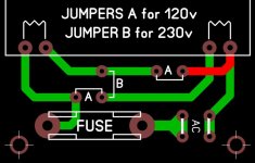
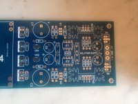
Pwr Supply PCB: I am now shipping the revised boards that include jumpers allowing the builder to configure for either 120v or 230v AC systems.
... In any case it is a reasonable thing and I will add a part pad to the IO PCB. Thank you for sharing!
Changes ...
IO PCB: Per my previous commitment I have added a capacitor pad to output of the 12v regulator that powers the relays. I have also added support for alternate grounding schemes for the XLR connectors. As a builder you must now either add a wire jumper to the system ground or to the chassis as is pro audio practice. The inputs are grounded separate from the outputs. You must properly terminate both the input XLRs and the output XLRs. If you fail to do that ground will float unterminated.
Pwr Supply PCB: I am now shipping the revised boards that include jumpers allowing the builder to configure for either 120v or 230v AC systems.
Attachments
I used those, very nice pots, pins required slight bending, but worked well.At last my order of 4k7 pots arrived so can get on with the build
CPC still have 90 in stock.
https://cpc.farnell.com/omeg/pc2g16eco4k7a/pot-dual-gang-lin-4k7/dp/RE04429
Thanks Carl for your continued work.Changes ...
IO PCB: Per my previous commitment I have added a capacitor pad to output of the 12v regulator that powers the relays. I have also added support for alternate grounding schemes for the XLR connectors. As a builder you must now either add a wire jumper to the system ground or to the chassis as is pro audio practice. The inputs are grounded separate from the outputs. You must properly terminate both the input XLRs and the output XLRs. If you fail to do that ground will float unterminated.
Pwr Supply PCB: I am now shipping the revised boards that include jumpers allowing the builder to configure for either 120v or 230v AC systems.
I'll don't have all my parts yet, but I'll be doing a little head scratching with 230V. I'll be sure to post once I get started.
I used those, very nice pots, pins required slight bending, but worked well.
Yes, I was surprised that the front/rear pin spacing was a bit out. I assumed standard spacing, but it was not an issue. I didn't feel confident in the quality of the Alps clones given the very low cost but I have used Omegs before with no issues.
Hi Carl,
Just got my boards today, looks very nice... i saw that you have added a diode pad for each relay...cool do not have to solder it behind the PCB.
By the way what is the suggest capacitor and is value that you have added to output of the 12v regulator that powers the relays.
Thanks

Just got my boards today, looks very nice... i saw that you have added a diode pad for each relay...cool do not have to solder it behind the PCB.
By the way what is the suggest capacitor and is value that you have added to output of the 12v regulator that powers the relays.
Thanks

Hi Carl,Yup, that's it minus the Lorlin front panel switch. Mouser stocks them now.
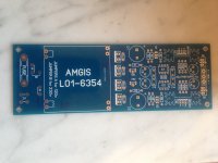
I just saw that you did not send the Adjust Power Supply board but the Fixed Power supply PCB, but i do not understand because there are the label "ADJ PWR SUPPLY" printed on it, see pictures
Attachments
Last edited:
Hi Carl,
Just got my boards today, looks very nice... i saw that you have added a diode pad for each relay...cool do not have to solder it behind the PCB.
By the way what is the suggest capacitor and is value that you have added to output of the 12v regulator that powers the relays.
Thanks
The pad added to the output of the 12v regulator is intended to accept a tantalum 10uF to 22uF capacitor. It most likely will not be required but is harmless in any case. Enjoy!
NOTE: Don't forget to ground the XLRs on the revised IO board.
Hi Carl,
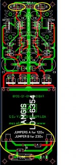
I just saw that you did not send the Adjust Power Supply board but the Fixed Power supply PCB, but i do not understand because there are the label "ADJ PWR SUPPLY" printed on it, see pictures
The bubbles at the top are the rail voltage adjustment pots and the large bubble at the bottom is where you select input AC voltage. Once assembled you will have a premium grade series regulated adjustable power supply
Attachments
The bubbles at the top are the rail voltage adjustment pots and the large bubble at the bottom is where you select input AC voltage. Once assembled you will have a premium grade series regulated adjustable power supply
Yes i got this PCB, but unfortunately i got all my component for the other one.....i followed this adjust power supply schematic.
Could you post the new schematic and boom list thanks
Attachments
Yes i got this PCB, but unfortunately i got all my component for the other one.....i followed this adjust power supply schematic.
Could you post the new schematic and boom list thanks
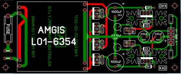
Aah, okay. That is because per your request, we sent you our power supply PCB that easily adjusts from 120v to 230v inputs. The version that you were expecting does not support that easy change. In any case the good news is that they share many parts in common.
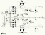
Here is the schematic and BOM for the power supply that we shipped you.
Attachments
Carl,
is it possible to 1 of this Regulated PWR Board.?
If so i would like to purchase 1.
Rick G
Sure,
For people within the US we can do ...
1 PCB for $10 (including the cost to ship) or ...
3 PCB for $20 (including the cost to ship)
Simply message me should you want to proceed.
The cost of shipping would a bit higher for those outside the US but we try to keep that reasonable as well.
Aah, okay. That is because per your request, we sent you our power supply PCB that easily adjusts from 120v to 230v inputs. The version that you were expecting does not support that easy change. In any case the good news is that they share many parts in common.
Here is the schematic and BOM for the power supply that we shipped you.
Be aware. These op amp supplies are not short circuit protected.
I'd be interested in recommendations, too.
I'm in the process of procuring a case for the Self preamp and was wondering what you all use for standoff's or risers?
Peter
I'm in the process of procuring a case for the Self preamp and was wondering what you all use for standoff's or risers?
Peter
I use the M3 threaded nylon hex standoffs. They can be purchased everywhere.
Ebay is an especially good source. Amazon works too.
- Home
- Source & Line
- Analog Line Level
- Doug Self Preamp from Linear Audio #5