I've not connected safety earth (PE) under those circumstances. If you want to be certain there is no way for mains to get to the chassis, fuse the low voltage supply. The only other way it could would be via the interconnects and that would depend on the precautions taken in the connected equipment
Thank you Matt, i will do so. Pictures will come as soon as something interesting happens.
There is an old Thread that includes this Safety discussion with lots of detailed diagrams..................One question i have right now is that i think i will put the power supply in a seperate box and i'm not sure what to do with the safety ground. Is it OK to use safety ground on the power supply only or does the preamp chassis need safety ground as well? IE through the power supply line? If that the case, how does one keep audio ground separate? .............
understanding star grounding
Last edited:
Thanks Andrew, that's a good read for this evening.There is an old Thread that includes this Safety discussion with lots of detailed diagrams.
understanding star grounding
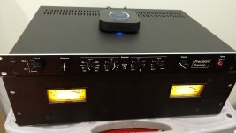
Honey Badger and Doug Self Preamp
Thanks to Doug Self for the design. Thanks Carl Huff for prompt PCB shipment and quick email replies.
Front Panel Express have done a very quality job with these panels. I highly recommend the company.
Thank you everyone for your help at the forums! I couldn't have done it without your help.
Thanks to Doug Self for the design. Thanks Carl Huff for prompt PCB shipment and quick email replies.
Front Panel Express have done a very quality job with these panels. I highly recommend the company.
Thank you everyone for your help at the forums! I couldn't have done it without your help.
Attachments
Nice Job!
Rick
Rick, your panel design files have helped a lot. Thank you!
Last edited:
Rick, your panel design files have helped a lot. Thank you!
the Original files were from Carl, I just modified them. Glad they were helpful
Having read the thread recommended by AndrewT a few post back and thereafter the article about audio component grounding and interconnection i think i'll keep it simple and use one chassis for everything, use star ground, and see if it humms. I thought i could skip safety earth in the two chassis solution but i now see that you shouldn't.
This leaves me wondering though why devices with wall warts don't require a safety earth connection and consequently why there are no symmetrical wall wart power supplies.
I do notice on many build photo's in this thread extra parts ie from rca chassis to ground or from power ground to safety earth. Is there a recommendation in this particular situation?
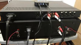
Also, how is the pin1 connection made? As i can tell from the photo's pin1 is routed to power ground through the main pcb. Is there something extra to be done around the XLR connectors to follow the recommendation to take the shortest path? Hope you guys don't mind my rambling or asking what should be obvious.")
This leaves me wondering though why devices with wall warts don't require a safety earth connection and consequently why there are no symmetrical wall wart power supplies.
I do notice on many build photo's in this thread extra parts ie from rca chassis to ground or from power ground to safety earth. Is there a recommendation in this particular situation?
Also, how is the pin1 connection made? As i can tell from the photo's pin1 is routed to power ground through the main pcb. Is there something extra to be done around the XLR connectors to follow the recommendation to take the shortest path? Hope you guys don't mind my rambling or asking what should be obvious.
Well I'm no longer sure two boxes have real benefits beside transformer noise. So I think it's going to be a one chassis preamp with mains in it. Except that I'm overlooking other advantages of a separate psu chassis.Have you decided that mains voltage could get into the preamp chassis?
some/many wallwart power supplies are ClassII = double insulated and guaranteed by design and construction to be safe without any connection to Protective Earth. All these ClassII have the concentric squares symbol printed on the labelling...................
This leaves me wondering though why devices with wall warts don't require a safety earth connection and consequently why there are no symmetrical wall wart power supplies.
Pin1 is the connector for the screen of a cable.I do notice on many build photo's in this thread extra parts ie from rca chassis to ground or from power ground to safety earth. Is there a recommendation in this particular situation?
Also, how is the pin1 connection made? As i can tell from the photo's pin1 is routed to power ground through the main pcb. Is there something extra to be done around the XLR connectors to follow the recommendation to take the shortest path? Hope you guys don't mind my rambling or asking what should be obvious.
That screen is an extension of the enclosure. The screen goes direct to the enclosure via pin1.
Pin1 does not get connected to the audio.
Attachments
Last edited:
Thanks Andrew I thought the same only the connector in the BOM are made of plastic so I wondered how it contacts the chassis.some/many wallwart power supplies are ClassII = double insulated and guaranteed by design and construction to be safe without any connection to Protective Earth. All these ClassII have the concentric squares symbol printed on the labelling.Pin1 is the connector for the screen of a cable.
That screen is an extension of the enclosure. The screen goes direct to the enclosure via pin1.
Pin1 does not get connected to the audio.
Thanks to Doug Self for the design. Thanks Carl Huff for prompt PCB shipment and quick email replies.
Front Panel Express have done a very quality job with these panels. I highly recommend the company.
Thank you everyone for your help at the forums! I couldn't have done it without your help.
Beautiful, well done!
Jan
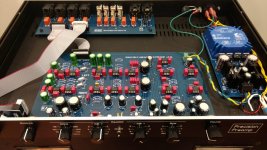
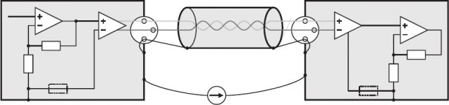
A closer look revealed a small sharp contact to touch the chassis. It goes inside the connector where it contact the XLR plug's shell. On the pcb this contact is on an isolated island. The pin 1 is on the ground plane. So if one uses cables with the shield connected to the plugs shell and pin 1 everything should be OK right?A short wide wire made from many fine strands to connect Pin1 to enclosure. If there are two screws/bolts fixing the XLR socket then a lead to each screw would be slightly lower impedance.
A bit like a tiny version of the Earth strap from engine to car chassis.
The "ground plane" is probably carrying audio signals.
That is NOT where pin1 connects to.
Pin1 connects the screen to the enclosure, because the screen is an extension of the enclosure.
See diagram post914
some reading:
Pin 1 Problem
Pin 1 Revisited
a Test procedure:
http://pin1problem.com/as032.pdf
That is NOT where pin1 connects to.
Pin1 connects the screen to the enclosure, because the screen is an extension of the enclosure.
See diagram post914
some reading:
Pin 1 Problem
Pin 1 Revisited
a Test procedure:
http://pin1problem.com/as032.pdf
Last edited:
- Home
- Source & Line
- Analog Line Level
- Doug Self Preamp from Linear Audio #5