By the way, anyone knows if there is a place at where you can source both the AMGIS L01-6354 transformer (for the power supply) and the LM4562 Op Amps? Digikey does not stock the op amp anymore unfortunately
found my lm4562 at Newark yesterday , they still have some.
I didn't receive a front panel template. I am just going to wait for those as I still have to build the darn thing when my parts come in.
If Carl posts the template, then we can see about the cost of doing a custom punch job for one of the DIYAudio cases. They now offer custom punching, and a $60 charge (I think) for transferring a pdf file into a CNC/AutoCAD file.
If anyone can convert what we may get from Carl, the cost would be much less.
I hope Carl posts files for both the original input board as well as the revised input board.
Drilling Templates
I have built several projects without the aid of a template for FP/ BP work, unfortunately. If we can get a shared generic template for FP and BP work then we might just be starting a trend. After all, the front and rear panel design contribute massively to the WAF. I would ask any qualified participants to contribute what they can (to Jan Didden?) so as to store a "library" of possible designs.That would be great. Quite a bit more drilling than when I build my Pass BA-3 pre. Since it was point to point wiring things didn't have to line up perfectly!
Even if you don't use the Front Panel Express service you can still use their software to lay out a panel. It offers all kinds of pre-defined hole and cut-out shapes and it is very easy to accurately position things. You can then print it out and use as a template. Make sure you have calibrated your printer for 1:1 output of course.
Jan
Jan
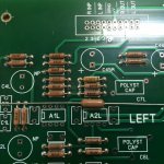
Will they fit the PCB’s?
Hello Builders,
Will Vishay Dale RN60 resistors fit these PCB’s. They are mil-spec ¼ watt resistors, larger than the typical ¼ resistor. These are 0.344 +- 0.031 inches ~ 3/8 of an inch.
I have most required values in stock. Will they fit the PCB’s?
Thanks
DT
Hello Builders,
Will Vishay Dale RN60 resistors fit these PCB’s. They are mil-spec ¼ watt resistors, larger than the typical ¼ resistor. These are 0.344 +- 0.031 inches ~ 3/8 of an inch.
I have most required values in stock. Will they fit the PCB’s?
Thanks
DT
Thank You
That is good detailed information.
Thank You
DT
Hi DT,
Unfortunately Dale RN60 slightly to big, but Dale RN55D will fit.
Best regards.
That is good detailed information.
Thank You
DT
Assembly
I have built quite a few things in my life. Sometimes it is frustrating getting all the prefabricated parts & pieces lined up parallel, all the faces in a line and all the screws or bolts lining up with the bolt holes.
For example, it is not only getting all the XLR he’s and she’s to fit the IO PCB drill pattern it is also getting those XLR plugs to mate up to the drill pattern of the rear plate at the same time. It is quite possible to solder all the IO plugs to the IO PCB and not have them “fit” the drill pattern of the rear panel. The PCB is precisely laid out and the rear panel is precisely laid out however there is some wiggle room when the devices are soldered one at a time to the PCB.
To avoid the “oh s**t” what do I do now moment, I think it might be a good idea loosely attach the components to a jig (drilled precisely as the rear panel is drilled) then carefully tease all the little legs into the drill pattern of the IO PCB. Once everything is where it wants to be snug up the fasteners then solder tack and anchor everything in place. No more tears and kicking the dog.
Thoughts?
DT
Even if you don't use the Front Panel Express service you can still use their software to lay out a panel. It offers all kinds of pre-defined hole and cut-out shapes and it is very easy to accurately position things. You can then print it out and use as a template. Make sure you have calibrated your printer for 1:1 output of course.
Jan
I have built quite a few things in my life. Sometimes it is frustrating getting all the prefabricated parts & pieces lined up parallel, all the faces in a line and all the screws or bolts lining up with the bolt holes.
For example, it is not only getting all the XLR he’s and she’s to fit the IO PCB drill pattern it is also getting those XLR plugs to mate up to the drill pattern of the rear plate at the same time. It is quite possible to solder all the IO plugs to the IO PCB and not have them “fit” the drill pattern of the rear panel. The PCB is precisely laid out and the rear panel is precisely laid out however there is some wiggle room when the devices are soldered one at a time to the PCB.
To avoid the “oh s**t” what do I do now moment, I think it might be a good idea loosely attach the components to a jig (drilled precisely as the rear panel is drilled) then carefully tease all the little legs into the drill pattern of the IO PCB. Once everything is where it wants to be snug up the fasteners then solder tack and anchor everything in place. No more tears and kicking the dog.
Thoughts?
DT
- Home
- Source & Line
- Analog Line Level
- Doug Self Preamp from Linear Audio #5