I too noticed that the L9110H data sheet fails to define many, if not most, of the parameters an engineer would need to be comfortable that this chip would work reliably in a high-volume commercial design. As an example of a "real" data sheet for a driver chip, consider the SN754410NE from TI. Characteristics of its inputs and outputs are properly defined. Sadly, at the moment, it appears to be in very short supply.
Infra-red remote, rotary encoder and related display is straightforward stuff using an Arduino. I've done one myself but it controls the volume via a digital volume control chip (MAS6116) and, whichever chip any solution uses, provides specific attenuation / gain dependent on the control data sent to the chip. Sending control signals to a motorised pot is not difficult either but you only send up/down control signals to the motor.My plan was to use a simple Arduino Nano processor. An infra-red receiver reads from a standard hand-held remote control and spins the motor thru a simple bridge circuit. I had planned to build the whole thing on the back of a PCB that has a display showing volume level relative to zero. Overall pretty simple.
As there's no feedback from the motor to show that it's reached fully min or max, how can you determine the current volume level?
I completely agree with your comments about the display for a motorised potentiometer (for digital volume controls/ attenuators, there is value in showing the current setting).Obviously you can’t so having a display for that is useless. The question could be what would a controller do at power up and down? Nothing or back off the volume. It is possible to measure the operating and stall motor current but is it necessary?
As far as what to do at power up and power down, I would suggest that doing nothing to the motorised pot is the best approach. For a digital volume control chip, the normal approach would be to save all current settings on power down and reinstate them on power up. These approaches mirror what you get with purely manual controls.
I think rsavas has it right. No display is the answer, especially since the volume control is the only feature being remote controlled.
Digipots and a phone app that controls everything (ie: selected input, balance, tone controls and volume)? Would it be worth the bother?
Digipots and a phone app that controls everything (ie: selected input, balance, tone controls and volume)? Would it be worth the bother?
Excellent point: there is no direct way to display the position of a motorized pot driven by an Arduino on an LCD display. Fortunately, it would be redundant information as the position of the pot would be visible with an index mark on the pot's knob. Which really brings up the issue that using an Arduino to only control a motorized pot is massive overkill. The ability of the Arduino to drive an LCD just begs to be used. Maybe the Arduino could be used to display diagnostic information, like the +/- voltage rails. Or the temperature of the linear regulators. Or, if you are still using diodes in the rectifier bridge with an inadequate voltage rating, you could display their temperature...
As for what other functions the micro should have, Mr. Self notes in his book that some provision should be made to prevent the motor from remaining on longer than it takes for full rotation. He mentions sitting on the remote as an example. If the preamp is being used with a powerful amp and efficient speakers, I would argue that an accidental full rotation must absolutely be avoided, but not just to save the pot's motor. I would argue for code that only allows a few db of volume increase before the "up" button must be released and then reasserted. Ergonomically, if one is accustomed to repeatedly pressing the "up" button until the desired volume is reached, you might never even notice that the "limit" function is there.
The micro could also control the mute relay, both in response to a button press, and to accomplish the initial delay after turn on.
The micro could also control the mute relay, both in response to a button press, and to accomplish the initial delay after turn on.
I personally find that there is no display needed if you use a motor pot, and I like the ergonomics and aesthetics of just looking at the knob's index or marker instead of looking at the digital number on a display.
But if you (as in the uC) want to know the pot's rotation, you can build a hybrid system with a digital potentiometer to actually control the gain and the pot purely as HMI device (human machine interface, in case you don't use this term). The Arduino reads the pot's wiper voltage and knows where the pot is, and then sets the digital pot to match it. This will also attract builders who believe a sliding pot is An Evil Thing, and will attract perfectionist engineers who cannot tolerate the channel imbalance of mechanical stereo pots.
I believe the LCDuino's volume control works this way -- mechanical pot purely provides input to the controller.
I've seen at least one volume control which does something more fancy in its UI -- it has a row of LEDs in a circular arc around the volume knob, and whenever the uC senses a change in the volume setting, it lights up the LEDs in this array for, say, 5 seconds, showing you where the current volume is. So, if you turn the volume from, say 10 o'clock to 12 o'clock, the LEDs from zero to 10 o'clock immediately light up, and as you turn the volume up, additional LEDs light up to show you how the volume is increasing. When you stop at 12 o'clock, it pauses for 5 secs with half the arc lit up, and then switches off all the LEDs. It does this even when you use the remote (the pot is a motor pot anyway). I love the fireworks but it may not be to your taste. This sort of thing is so easy to do with an Arduino and maybe a pair of LM3914 cascaded.
Take it one step further -- use two mechanical pots, one for volume, one for balance. Read both values into the uC, and then drive two separate digital pots with the sum of these inputs. (Of course, these days, only analog source users care about balance controls, it seems.)
About the danger of accidentally driving a remote volume control to full scale, I'd rather put the protection before the power amp if I could. I'd prefer to sense the input amplitude and trigger a 10:1 or 20:1 attenuation when the input reaches within 1-2dB of clipping levels. If it's implemented this way, it'll work with all preamps and sources.
But if you (as in the uC) want to know the pot's rotation, you can build a hybrid system with a digital potentiometer to actually control the gain and the pot purely as HMI device (human machine interface, in case you don't use this term). The Arduino reads the pot's wiper voltage and knows where the pot is, and then sets the digital pot to match it. This will also attract builders who believe a sliding pot is An Evil Thing, and will attract perfectionist engineers who cannot tolerate the channel imbalance of mechanical stereo pots.
I believe the LCDuino's volume control works this way -- mechanical pot purely provides input to the controller.
I've seen at least one volume control which does something more fancy in its UI -- it has a row of LEDs in a circular arc around the volume knob, and whenever the uC senses a change in the volume setting, it lights up the LEDs in this array for, say, 5 seconds, showing you where the current volume is. So, if you turn the volume from, say 10 o'clock to 12 o'clock, the LEDs from zero to 10 o'clock immediately light up, and as you turn the volume up, additional LEDs light up to show you how the volume is increasing. When you stop at 12 o'clock, it pauses for 5 secs with half the arc lit up, and then switches off all the LEDs. It does this even when you use the remote (the pot is a motor pot anyway). I love the fireworks
but it may not be to your taste. This sort of thing is so easy to do with an Arduino and maybe a pair of LM3914 cascaded.Take it one step further -- use two mechanical pots, one for volume, one for balance. Read both values into the uC, and then drive two separate digital pots with the sum of these inputs. (Of course, these days, only analog source users care about balance controls, it seems.)
About the danger of accidentally driving a remote volume control to full scale, I'd rather put the protection before the power amp if I could. I'd prefer to sense the input amplitude and trigger a 10:1 or 20:1 attenuation when the input reaches within 1-2dB of clipping levels. If it's implemented this way, it'll work with all preamps and sources.
Last edited:
If we were to go down the remote control direction this could range from
On the subject of how to handle reaching the end stops while operating the remote -from what I can remember about my old Arcam preamp, when the motorised alps pot hit the end stops, it simply slipped the clutch.
- simply driving volume up /down for a motorised alp pot, right through to
- digital potentiometers for all five existing variable controls (that's bal, vol, bass level, bass freq, treble level, treble freq,), together with source selection and output mute.
On the subject of how to handle reaching the end stops while operating the remote -from what I can remember about my old Arcam preamp, when the motorised alps pot hit the end stops, it simply slipped the clutch.
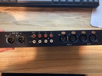
Rear Panel FPD file
glenv6,
Here is a rear panel layout for a 1U case. I cannot remember who sent it to me, so thank you whoever you are.
Dropbox - REAR_PANEL_1U.fpd - Simplify your life
I ordered a rear panel from this FPD and unfortunately it has a few inaccuracies that are sufficient for the IO board not to fit.
Front Panel Express are extremely accurate, has anyone else had an issue with this file?
Carl, does your PCB software allow to export the PCB as DXF? I've used that method in the past to make perfectly aligned layouts.
If not, would it be possible to provide the exact distances of the XLR and RCA sockets from the PCB layout itself ?
Attachments
I ordered a rear panel from this FPD and unfortunately it has a few inaccuracies that are sufficient for the IO board not to fit.
Front Panel Express are extremely accurate, has anyone else had an issue with this file?
Carl, does your PCB software allow to export the PCB as DXF? I've used that method in the past to make perfectly aligned layouts.
If not, would it be possible to provide the exact distances of the XLR and RCA sockets from the PCB layout itself ?
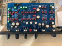
 I used that file, but I adapted it to a 2U chassis. I verified placement of all the parts using measurements of Carl’s I found somewhere in this thread, and I measured my finished board, which I had to do anyway to fit the 2U back. I don’t recall making any changes to the component spacing, but it’s possible that I did.
Actually, you can if you use a dual pot and use the 2nd section for position feedback and limiting.Infra-red remote, rotary encoder and related display is straightforward stuff using an Arduino. I've done one myself but it controls the volume via a digital volume control chip (MAS6116) and, whichever chip any solution uses, provides specific attenuation / gain dependent on the control data sent to the chip. Sending control signals to a motorised pot is not difficult either but you only send up/down control signals to the motor.
As there's no feedback from the motor to show that it's reached fully min or max, how can you determine the current volume level?
Did that many years ago. I had to use discrete logic gates but today with a Rpi or similar it would be a no-brainer.
Jan
Attachments
That would be helpful, just as an additional sanity check.Sure, I can do the same for the front panel
I made a few changes to the front panel templates, they look great but I overlooked a few details and they have a 2 minor issues:
1) I didn't account for the pot range correctly, so the knob marker doesn't align properly to the markers on the extremes.
2) The cutout intended for the volume knob is slightly off-center so I can't use the pot I originally planned on using.
Unfortunately I am a perfectionist when it comes to the panels and I will re-order a new one.
If someone has a blank Slimline 1U panel, and doesn't mind these minor issues, I'd be happy to swap and you could save quite a bit.
Otherwise it will likely get recycled some time soon.
Attachments
- Home
- Source & Line
- Analog Line Level
- Doug Self Preamp from Linear Audio #5