The color is likely just a preference.
I am guessing that D7 and D8 are not critical. It looks like they are there to bleed off a handful of milliamps and to indicate on or off for both the positive leg and negative leg. The color is likely just a preference. The 3 mm part of the specification is to fit the circuit board.
DT
I, too, have questions about those devices. Can someone please share this information?
I am guessing that D7 and D8 are not critical. It looks like they are there to bleed off a handful of milliamps and to indicate on or off for both the positive leg and negative leg. The color is likely just a preference. The 3 mm part of the specification is to fit the circuit board.
DT
I am guessing that D7 and D8 are not critical. It looks like they are there to bleed off a handful of milliamps and to indicate on or off for both the positive leg and negative leg. The color is likely just a preference. The 3 mm part of the specification is to fit the circuit board.
DT
DualTriode is right. There is nothing special about those LEDs. Sorry that I missed your question Harold.
I reduced the length of the front panel drill template so it fits on an 8 1/2 x 11 paper. I also made a drill template for the 5 channel rear template. I did drill a panel based on the template and it seems to fit but one of you may want to test it for yourself before you have a panel made. The line represents the bottom of the PCB not the edge of the panel.
Attachments
Last edited:
Guys,
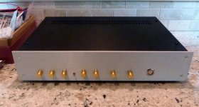
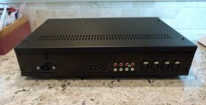
Almost done, waiting on a ribbon coming in the mail to try out. Here are a few pics of the pre in a pesante 2U chassis from the DIY store. I hand made templates for the front and rear out of paper and did the cutouts with various drill bit sizes and hand files. The rear cutouts were a real challenge, I hate working with steel, aluminum is so much easier. I'm planning to print the front panel graphic on a clear plastic transparency and paste it over the knobs. I don't know if I like the gold knobs but they were cheap, might try some silver or black ones. Tried out the PSU works like a charm, can't wait to give it a listen.
Paul
Attachments
Thanks
Got to think about the layout.. my volume control is remote, so it is connected by wires to the main pcb. I don't those near the PS. The Selector could go near the PS as no signals go that way. So I shall be adding, in addition to what you show, an IR receiver (for remote volume and mute control) and a local mute switch. I really want to avoid a forest of wires.
It does seem pretty good. As Jan Didden pointed out a while back the front and rear plates can be sent off to Schaeffer (in Europe) for machining to the design in the Front Panel Designer package.Hi George,
2U case dimensions are H ~3.15", W ~ 17", D~11.8". Heavy steel construction, for 70 bucks delivered with no shipping (in US) it is a great deal.
Paul
Got to think about the layout.. my volume control is remote, so it is connected by wires to the main pcb. I don't those near the PS. The Selector could go near the PS as no signals go that way. So I shall be adding, in addition to what you show, an IR receiver (for remote volume and mute control) and a local mute switch. I really want to avoid a forest of wires.
DS Preamp
Yeah, I finally have my working on the bench. Very nice and a thank you to Doug and Carl for making it happen.
Just playing MP3s through a Fostex, barely ok. My plan is to use this as the front end to a F6 I have ready.
Just need to complete the cabinet.
A Self + Pass = greatness.
Yeah, I finally have my working on the bench. Very nice and a thank you to Doug and Carl for making it happen.
Just playing MP3s through a Fostex, barely ok. My plan is to use this as the front end to a F6 I have ready.
Just need to complete the cabinet.
A Self + Pass = greatness.
Attachments
Case Size
The Selector is off board and so is my (remote) volume control. I plan to use larger knobs for these two items anyway. Also I have remote mute and an indicator and receiver to mount, so for flexibility I am going for a 2U case...the remote volume control is bulky and I wanted a route for its wiring that could avoid going near power lines.
How high a case does it need? Fits a 1U or need to go 2U? Thanks.
The Selector is off board and so is my (remote) volume control. I plan to use larger knobs for these two items anyway. Also I have remote mute and an indicator and receiver to mount, so for flexibility I am going for a 2U case...the remote volume control is bulky and I wanted a route for its wiring that could avoid going near power lines.
The Selector is off board and so is my (remote) volume control. I plan to use larger knobs for these two items anyway. Also I have remote mute and an indicator and receiver to mount, so for flexibility I am going for a 2U case...the remote volume control is bulky and I wanted a route for its wiring that could avoid going near power lines.
George
what did you find for a remote?

George
what did you find for a remote?
Hi,
I built a remote transmitter / receiver from Infrared Remote Control for Audio . The transmitter is a bit bulky, but uses Sony codes so you can get an intelligent remote... Logitech for example, to control the volume and mute of the amplifier.
I use a relay to make / break the link on the PS as mute method.. it will have a front panel make / break as well as a remote make break.
The build is very simple and it can use the 17V supply directly.
What I did this Winter
Hi,
As there was some interest in the remote setup that I made I thought that I would show some photos.
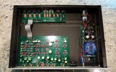
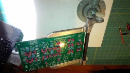
On the large photo you can see the main PCB with the new IO board connected, as well as the selector.
On the right .. just out of site is the PS. I did not use this in the test setup as I wanted to keep the mains power out of all the wires. I am testing with a bench PS.
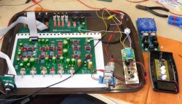
The volume control is an Alps mounted on a small PCB with screw connectors (not yet connected to the main board). The two small boards to the right are (1) the remote receiver and (2) a small board to mount the relay. The remote board controls the volume and mute. The relay makes/breaks the 12V connection on the IO board thus muting the system. I wanted to show that the system is in mute mode and the LEDs in the chromium switch (above the relay board) needs 12V, so I connected its LED across the 12V terminal on the OP board. Thus, when muted (open circuit), the LED glows. Pressing the button also sets muting, so I have local and remote muting setting. The button overrides the remote muting.
I also wanted to use the same kind of switch to control power on/off from the front panel. Conveniently the Selector has a 12V supply that can be used to power the on/off LED. All of this is because tests (so far) have shown the 5V available from the remote receiver board to be insufficient for the LEDs .
The Alps volume pot is bulky and for access needs to be mounted to one side of the main PCB. So, the final layout will be with the Selector far left, volume far right, mute and on/off centre, low down, and the pots on the main PCB centre, high up. The IR receiver aperture will be where ever I can conveniently position it. Hence the need for a 2U case.
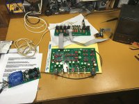
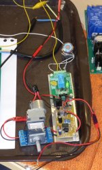
The second photo shows a little more detail of the remote receiver and the relay mount. The relay PCB was purchased complete (China!) for around £5 including postage and just provides a robust and tidy mount for the relay and its connections. It needed a little modification so that it could be driven directly by the receiver mute feature but so far has worked perfectly.
Any questions , just ask
Hi,
As there was some interest in the remote setup that I made I thought that I would show some photos.
On the large photo you can see the main PCB with the new IO board connected, as well as the selector.
On the right .. just out of site is the PS. I did not use this in the test setup as I wanted to keep the mains power out of all the wires. I am testing with a bench PS.
The volume control is an Alps mounted on a small PCB with screw connectors (not yet connected to the main board). The two small boards to the right are (1) the remote receiver and (2) a small board to mount the relay. The remote board controls the volume and mute. The relay makes/breaks the 12V connection on the IO board thus muting the system. I wanted to show that the system is in mute mode and the LEDs in the chromium switch (above the relay board) needs 12V, so I connected its LED across the 12V terminal on the OP board. Thus, when muted (open circuit), the LED glows. Pressing the button also sets muting, so I have local and remote muting setting. The button overrides the remote muting.
I also wanted to use the same kind of switch to control power on/off from the front panel. Conveniently the Selector has a 12V supply that can be used to power the on/off LED. All of this is because tests (so far) have shown the 5V available from the remote receiver board to be insufficient for the LEDs .
The Alps volume pot is bulky and for access needs to be mounted to one side of the main PCB. So, the final layout will be with the Selector far left, volume far right, mute and on/off centre, low down, and the pots on the main PCB centre, high up. The IR receiver aperture will be where ever I can conveniently position it. Hence the need for a 2U case.
The second photo shows a little more detail of the remote receiver and the relay mount. The relay PCB was purchased complete (China!) for around £5 including postage and just provides a robust and tidy mount for the relay and its connections. It needed a little modification so that it could be driven directly by the receiver mute feature but so far has worked perfectly.
Any questions , just ask
Attachments
Last edited:
- Home
- Source & Line
- Analog Line Level
- Doug Self Preamp from Linear Audio #5