Hi tmrost,I like this design and looks like a nice upgrade to the preamp. Do you have design files and software available? I would like to add something like this to my preamp. Looks great!
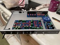
I have KiCad files of the PCBs which I modified+the digipot board, and my SW for the Grand Central M4 (this SW will only work on an M4 as there are HW dependencies like a 2nd SPI and power down detection). Just let me know what exactly you need and I can send it to you.
Of course, there is a front panel fpd file as well.
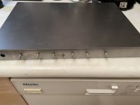
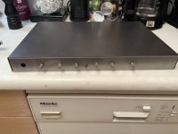
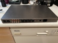
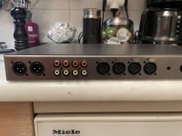
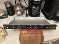
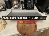
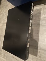
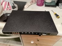
The display is an SSD1331 RGB display which fits into a 1U case.
Currently, there is zipper noise. It should be possible to drastically reduce it by implementing single step ramps for the digipots in the SW. I was just too lazy to do it, so far
")
In general: I wouldn't call this mod an improvement. I did it for 2 reasons: remote control and a cooler HMI (and fun, of course). Noise/distortion may have suffered from this change.
That would be great if you can send me the files and SW you have. Do you have SW for remote control? This looks like fun, and Thank you!Hi tmrost,
I have KiCad files of the PCBs which I modified+the digipot board, and my SW for the Grand Central M4 (this SW will only work on an M4 as there are HW dependencies like a 2nd SPI and power down detection). Just let me know what exactly you need and I can send it to you.
Of course, there is a front panel fpd file as well.
The display is an SSD1331 RGB display which fits into a 1U case.
Currently, there is zipper noise. It should be possible to drastically reduce it by implementing single step ramps for the digipots in the SW. I was just too lazy to do it, so far
In general: I wouldn't call this mod an improvement. I did it for 2 reasons: remote control and a cooler HMI (and fun, of course). Noise/distortion may have suffered from this change.
Is there any chance I could purchase one of your boards, Just the PCB if you have any left? And if you have one of these AMGIS L01-6354, Digikey is out of stock.Schematic and BOM for Power Supply
Here is the schematic and BOM for the project power supply. It is a subtle variation on the one pointed to by Mr Self earlier in this thread. It is from his "Small Signal Audio Design" book.

The BOM in Excel spreadsheet form is here ...
https://dl.dropboxusercontent.com/u/33294265/DSELF_PWR_SUPPLY_BOM.xls
Please let me know. Will pay with PayPal.
https://www.digikey.ca/en/products/detail/talema-group-llc/70054K/3881348 is a direct replacement for L01-6354. The 25VA (L01-6364) version will fit the same footprint too, just a bit taller.
Perfect... Thankshttps://www.digikey.ca/en/products/detail/talema-group-llc/70054K/3881348 is a direct replacement for L01-6354. The 25VA (L01-6364) version will fit the same footprint too, just a bit taller.
Hi Carl, just wondering if PCBs/Kits are still available? Thanks a lot!'YES!' Check your personal messages ...
Hi Carl, just wondering if PCBs/Kits are still available? Thanks a lot!
Yup, still have them. Check your messages for details
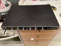
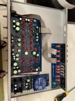
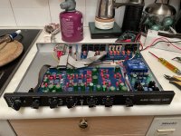
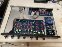
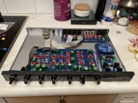
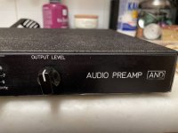
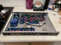
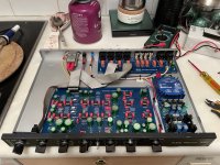
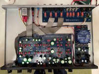
Just want to report that after two years of scrapping together parts, making various mistakes, getting help from the forum, screwing up the front panel order with Modushop and redoing it in laser cut baltic birch...the preamp was finally installed upstairs feeding my F6 and some A26 speakers. Fantastic pre-amp. At least until the bomb cyclone hit the west coast and my power went out. Turns out it doesn't work when there is no power. Oh well.
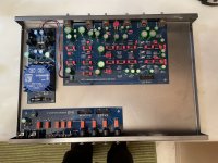
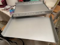
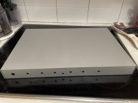
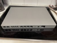
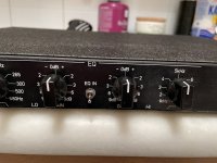
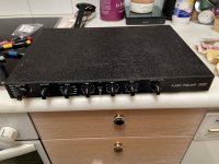
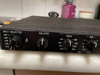
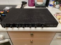
Here is the finished preamp. With the various stages to the end.
Attachments
-
 IMG_5041.jpeg273.8 KB · Views: 161
 -
 IMG_5042.jpeg355.8 KB · Views: 147
 -
 IMG_5043.jpeg343.1 KB · Views: 156
 -
 IMG_5044.jpeg352.1 KB · Views: 195
 -
 IMG_5045.jpeg542.4 KB · Views: 192
 -
 IMG_5051.jpeg469.7 KB · Views: 198
 -
 IMG_5053.jpeg338 KB · Views: 151
 -
 IMG_5052.jpeg369.5 KB · Views: 167
 -
 IMG_5070.jpeg477.9 KB · Views: 170
 -
 IMG_5071.jpeg467.2 KB · Views: 186
 -
 IMG_5093.jpeg528.8 KB · Views: 186
 -
 IMG_5083.jpeg431 KB · Views: 178
 -
 IMG_5082.jpeg316 KB · Views: 142
 -
 IMG_5081.jpeg779.7 KB · Views: 140
 -
 IMG_5080.jpeg950.3 KB · Views: 133
 -
 IMG_5098.jpeg696.3 KB · Views: 145
 -
 IMG_5097.jpeg709.8 KB · Views: 170
 -
 IMG_5096.jpeg634.1 KB · Views: 179
 -
 1674304652306291.jpeg219.4 KB · Views: 172
 -
 IMG_5094.jpeg366.7 KB · Views: 157
And then some more.
Attachments
-
 IMG_5121.jpeg632 KB · Views: 106
 -
 IMG_5123.jpeg545.2 KB · Views: 102
 -
 IMG_5122.jpeg651 KB · Views: 98
 -
 IMG_5111.jpeg569.5 KB · Views: 103
 -
 IMG_5110.jpeg550 KB · Views: 106
 -
 IMG_5105.jpeg415.6 KB · Views: 115
 -
 IMG_5106.jpeg418.1 KB · Views: 106
 -
 IMG_5107.jpeg405.1 KB · Views: 105
 -
 IMG_5093.jpeg528.8 KB · Views: 112
 -
 IMG_5104.jpeg526.6 KB · Views: 99
 -
 IMG_5105.jpeg415.6 KB · Views: 91
 -
 IMG_5106.jpeg418.1 KB · Views: 93
 -
 IMG_5107.jpeg405.1 KB · Views: 87
 -
 IMG_5108.jpeg589.1 KB · Views: 88
 -
 IMG_5109.jpeg532.7 KB · Views: 96
 -
 IMG_5110.jpeg550 KB · Views: 86
 -
 IMG_5111.jpeg569.5 KB · Views: 74
 -
 IMG_5121.jpeg632 KB · Views: 70
 -
 IMG_5122.jpeg651 KB · Views: 84
 -
 IMG_5123.jpeg545.2 KB · Views: 107
I made a template on AutoCAD with the files found in this thread and I designed an open box. Then I gave the plans to a friend that owns a laser cutting machine and another that bends the metal and he made it on two pieces. And here is the result.Awesome metal work
What tools did you use for cutting etc.?
I'd recommend to place the mains inlet on the other side so that there's no need to cross the mains and audio lines...
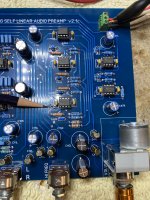
I finally got around to testing. I don't get any relay to work whilst rotating the selector switch. I certainly could have made some error(s) so I started to measure voltages.
While checking ICs for (+) (-) power this one has no negative (-) voltage supply. It seems I found a missing trace and so installed a jumper, shown. Now I have (-) volts to that IC.
However, I still have issues to troubleshoot (such as relays not switching) but before I go any further:
1. This board is a newer one to accept a remote volume control footprint. Has anyone built and tested their preamp with this particular board yet?
2. If in fact this board has not been built or tested, could there be other errors on it?
Attachments
TomLang said,"If in fact this board has not been built or tested, could there be other errors on it?"
Tom it appears that you mistakenly got a 1st generation prototype board. I remember a trace missing, but no other mistakes. Sorry about that, as a rule we do not ship prototype boards to customers.
As to your relay problem, I suggest you check your front panel switch build. If you need anything please let me know.
- Home
- Source & Line
- Analog Line Level
- Doug Self Preamp from Linear Audio #5